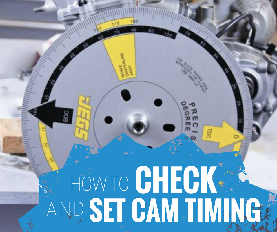
Today I'm going to cover how to check and set cam timing, which is something you can do if you have adjustable cam gears in your four stroke dirt bike engine. This is a procedure often performed by race engine builders to ensure the valvetrain performs just as they intend, and ultimately so that they extract the desired performance out of the engine. Adjustable cam gears typically aren't a stock option but are abundantly available in the aftermarket. The following text is exerted from my book, The Four Stroke Dirt Bike Engine Building Handbook, so if you find this info valuable please take a look at the entire book.
Degreeing the camshafts is the process of checking, and if necessary altering, the cam timing so that the timing is set perfectly to specified timing values. On stock and performance engines, cam timing can be off slightly due to manufacturing variations in parts such as the camshafts, cam gears, cam chain, cylinder, cylinder head, crankshaft, crankcase, and gaskets. With so many parts having an influence on cam timing, it is necessary to adjust and correct the timing so it coincides precisely with the desired timing values.
The biggest factor determining how the camshafts must be timed is whether the cam lobes are symmetrical or asymmetrical. Camshaft lobes that are symmetrical have opening and closing ramps that share the same profile. Asymmetrical cam lobes have opening and closing ramps with different profiles. Symmetric and asymmetric camshafts are timed differently. First we will focus on the timing of symmetrical camshafts.
Symmetric camshafts are timed most accurately by determining the position of the camshaft’s lobe center in relation to crankshaft position. A camshaft’s lobe center is where peak lift occurs, which is the most important timing event of the camshaft. Since the tip of the camshaft is rounded, it would be difficult to determine the lobe center by taking a direct measurement of peak valve lift. The opening and closing points of the camshaft are also of little use because the cam opens and closes gradually. This makes it difficult to determine the precise position in which the camshaft opens or closes the valves.
The lobe center position is a calculated value based on the position of the camshaft at two specific points of valve lift, typically with valve clearances set to zero. Normally the position of the camshaft is recorded at 0.050” (1.27mm) of lift as the valve opens and 0.050” (1.27mm) of lift when the valve closes. By recording the position of the camshaft at a specific valve lifts, the cam lobe is on a predictable portion of the opening and closing ramps. The center of the cam lobe is exactly in the middle of these two measurements.
To calculate the lobe center of a symmetrical cam lobe you will need to do the following:
1. Add the measured opening and closing timings together
2. Add 180 degrees to the sum
3. Divide the answer by 2
4. Subtract the smaller value of the two opening and closing numbers from the answer to reach the lobe center value.
Once the actual lobe center value has been determined on the engine, it can be compared to the specified lobe center timing presented by the manufacturer, aftermarket cam supplier, or the engine tuner. If the measured lobe center position coincides with the targeted position, all the work is done. If not, the cam gear will need to be adjusted so the timing is corrected.
If you are checking the timing on stock cams and lobe center information isn't presented, you will need to determine the lobe centers the manufacturer recommends. To do this, the opening and closing timing information supplied in the service manual can be used. Aftermarket camshafts should come with a timing card full of useful information to set the cams correctly if they are adjustable, otherwise the lobe centerline can be calculated if the opening and closing timings are known. If you don’t like math, there are plenty of lobe center calculators available on the internet you can use.
For the Kawasaki KX250F engine with the stock camshafts, the timing information is as follows:
Intake Opens 40° BTDC (Before Top Dead Center)
Intake Closes 72° ATDC (After Top Dead Center)
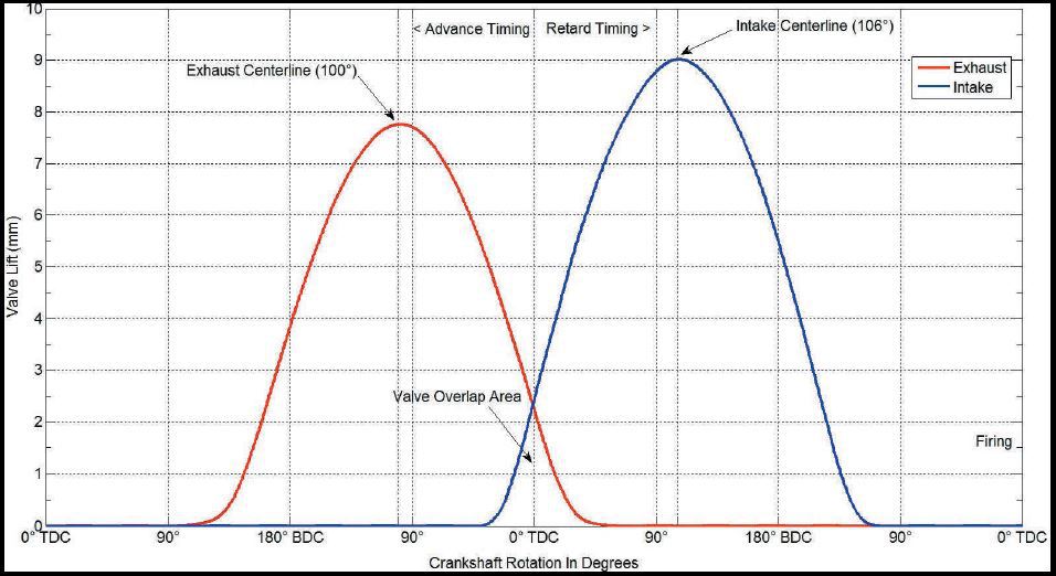
Intake Lobe Center = ((40 + 72 + 180) ÷ 2) - 40 = 106°
My calculated lobe center timing is 106°. When I check the cam timing, this will be the value the real engine hopefully yields. The lobe center for the exhaust cam can be found the same way. For the KX250F exhaust cam:
Exhaust Opens 69° BBDC (Before Bottom Dead Center)
Exhaust Closes 49° ATDC (After Top Dead Center)
Exhaust Lobe Center = ((69 + 49 + 180) ÷ 2) - 49 = 100°
Something not obvious I want to touch on is that if the intake opens after top dead center, a negative value for the opening should be used. If the exhaust closes before top dead center, a negative value should be used here as well.
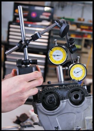
To start the process of checking the timing the valve clearances should be set to zero. Thicker shims can be used and zero clearance can be confirmed with a lash gauge. A degree wheel and pointer will need to be installed on the engine. There are many ways of attaching these items and each engine will provide its own challenges.
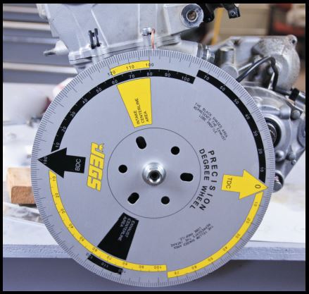
Here I’ve left the flywheel on and installed a couple washers behind the degree wheel to space the degree wheel from the flywheel. Then the flywheel nut is used to secure the degree wheel. The pointer can be made from welding rod, a coat hanger, or anything else you can find. I’ll be finding TDC with the cylinder head installed, so I used one of the exterior head bolts to secure the pointer. If you will be finding TDC with the head off, choose another location.
The biggest factor determining how the camshafts must be timed is whether the cam lobes are symmetrical or asymmetrical. Camshaft lobes that are symmetrical have opening and closing ramps that share the same profile. Asymmetrical cam lobes have opening and closing ramps with different profiles. Symmetric and asymmetric camshafts are timed differently. First we will focus on the timing of symmetrical camshafts.
Symmetric camshafts are timed most accurately by determining the position of the camshaft’s lobe center in relation to crankshaft position. A camshaft’s lobe center is where peak lift occurs, which is the most important timing event of the camshaft. Since the tip of the camshaft is rounded, it would be difficult to determine the lobe center by taking a direct measurement of peak valve lift. The opening and closing points of the camshaft are also of little use because the cam opens and closes gradually. This makes it difficult to determine the precise position in which the camshaft opens or closes the valves.
The lobe center position is a calculated value based on the position of the camshaft at two specific points of valve lift, typically with valve clearances set to zero. Normally the position of the camshaft is recorded at 0.050” (1.27mm) of lift as the valve opens and 0.050” (1.27mm) of lift when the valve closes. By recording the position of the camshaft at a specific valve lifts, the cam lobe is on a predictable portion of the opening and closing ramps. The center of the cam lobe is exactly in the middle of these two measurements.
To calculate the lobe center of a symmetrical cam lobe you will need to do the following:
1. Add the measured opening and closing timings together
2. Add 180 degrees to the sum
3. Divide the answer by 2
4. Subtract the smaller value of the two opening and closing numbers from the answer to reach the lobe center value.
Once the actual lobe center value has been determined on the engine, it can be compared to the specified lobe center timing presented by the manufacturer, aftermarket cam supplier, or the engine tuner. If the measured lobe center position coincides with the targeted position, all the work is done. If not, the cam gear will need to be adjusted so the timing is corrected.
If you are checking the timing on stock cams and lobe center information isn't presented, you will need to determine the lobe centers the manufacturer recommends. To do this, the opening and closing timing information supplied in the service manual can be used. Aftermarket camshafts should come with a timing card full of useful information to set the cams correctly if they are adjustable, otherwise the lobe centerline can be calculated if the opening and closing timings are known. If you don’t like math, there are plenty of lobe center calculators available on the internet you can use.
For the Kawasaki KX250F engine with the stock camshafts, the timing information is as follows:
Intake Opens 40° BTDC (Before Top Dead Center)
Intake Closes 72° ATDC (After Top Dead Center)
Intake Lobe Center = ((40 + 72 + 180) ÷ 2) - 40 = 106°
My calculated lobe center timing is 106°. When I check the cam timing, this will be the value the real engine hopefully yields. The lobe center for the exhaust cam can be found the same way. For the KX250F exhaust cam:
Exhaust Opens 69° BBDC (Before Bottom Dead Center)
Exhaust Closes 49° ATDC (After Top Dead Center)
Exhaust Lobe Center = ((69 + 49 + 180) ÷ 2) - 49 = 100°
Something not obvious I want to touch on is that if the intake opens after top dead center, a negative value for the opening should be used. If the exhaust closes before top dead center, a negative value should be used here as well.
To start the process of checking the timing the valve clearances should be set to zero. Thicker shims can be used and zero clearance can be confirmed with a lash gauge. A degree wheel and pointer will need to be installed on the engine. There are many ways of attaching these items and each engine will provide its own challenges.
Here I’ve left the flywheel on and installed a couple washers behind the degree wheel to space the degree wheel from the flywheel. Then the flywheel nut is used to secure the degree wheel. The pointer can be made from welding rod, a coat hanger, or anything else you can find. I’ll be finding TDC with the cylinder head installed, so I used one of the exterior head bolts to secure the pointer. If you will be finding TDC with the head off, choose another location.
Before the cams can be timed, TDC must be found. This can be done with the cylinder head on or off depending on the process you use. The piston dwells a few degrees at TDC so more accuracy than zeroing the degree wheel to the piston’s highest position is necessary. Similar to finding the cam lobe center, TDC can be found by measuring equal distances on the piston’s up and down stroke and then confirming that the degree wheel timing is equal on both sides at the measured distances. Dial indicators or piston stoppers are commonly used to do this.
HOT TIP: Piston stoppers can easily be made by removing the center section of a spark plug and then tapping a suitably sized threaded hole in the remaining part of the plug so a bolt and lock nut can be installed. The stopper can then be easily threaded into the spark plug hole.
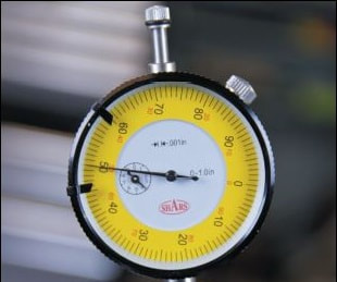
Whichever method of finding TDC you decide to use, start by moving the crankshaft to the approximate TDC position. Then without rotating the crankshaft move the degree wheel so that TDC on the wheel coincides with the pointer. Next, set up your piston stops or measure piston travel on both sides of TDC. In this example I’m using a dial indicator which extends through the spark plug hole down into the cylinder. I’ve decided to take measurements at 0.050” (1.27mm) of piston travel before and after TDC. At each measurement point the number of degrees indicated on the degree wheel before and after TDC should be the same if I have found true TDC.
HOT TIP: Piston stoppers can easily be made by removing the center section of a spark plug and then tapping a suitably sized threaded hole in the remaining part of the plug so a bolt and lock nut can be installed. The stopper can then be easily threaded into the spark plug hole.
Whichever method of finding TDC you decide to use, start by moving the crankshaft to the approximate TDC position. Then without rotating the crankshaft move the degree wheel so that TDC on the wheel coincides with the pointer. Next, set up your piston stops or measure piston travel on both sides of TDC. In this example I’m using a dial indicator which extends through the spark plug hole down into the cylinder. I’ve decided to take measurements at 0.050” (1.27mm) of piston travel before and after TDC. At each measurement point the number of degrees indicated on the degree wheel before and after TDC should be the same if I have found true TDC.
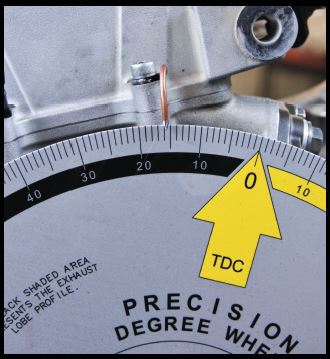 | 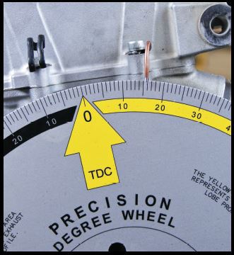 |
If the degree wheel values don’t read the same before and after TDC determine which way the wheel must be rotated so that the values become equal. Then carefully rotate the degree wheel without rotating the crankshaft to alter the degree wheel’s position. Once altered, recheck and confirm that true TDC has been found. This can be a tedious process but is extremely important for checking cam timing accurately. Repeat the procedure for checking TDC 3 - 5 times to ensure repeatability and accuracy.
After true TDC has been found, be extremely careful not to inadvertently move the degree wheel or pointer. Do not rotate the crankshaft using the nut securing the degree wheel to the crankshaft. Instead, use the primary drive gear nut or bolt to rotate the engine over.
Next, set up a dial indicator on the intake or exhaust lifter bucket, depending on which camshaft you are checking. You’ll have to use some ingenuity here in determining the best way to secure the dial indicator to the engine. I’ve used a flat piece of steel and secured it to the cam cap using the cylinder head cover holes. Make sure the indicator travels as parallel to the path of valve travel as possible for accurate readings. Also makes sure at least 0.060” (1.52mm) of travel from the indicator’s resting position is possible so adequate valve lift can be measured.
 |  |
Once the indicator has been set up, the cam timing can be checked. Whenever checking timing only rotate the engine over in the direction of engine rotation. Reversing engine rotation will result in inaccurate measurements due to the reversal of gear meshes and chain slack. If you miss a measurement point, rotate the engine over until you get back to the previous position.
Slowly rotate the engine over until 0.050” (1.27mm) of valve lift has occurred. Then record the position of the degree wheel. Next, rotate the engine until the cam begins to close the valve. Once only 0.050” of indicated valve lift remains record the position of the degree wheel. Repeat this process of checking opening and closing positions 3 - 5 times to check for repeatability before calculating the cam lobe center.
Once you are confident in your measurements proceed to calculate the cam lobe center. On the KX250F engine my intake lobe center is as follows:
Measured Intake Open (0.050” Lift) 39 ° BTDC
Measured Intake Closure (0.050” Lift) 74 ° ABDC
Intake Lobe Center = (( 39 + 74 + 180 ) ÷ 2 ) - 39 = 107.5°
On my stock KX250F engine the actual lobe center is 107.5°. At this point if I had adjustable cam gears, I could rotate the gear slightly so that the lobe center corresponded to the specified lobe center value. The same procedure is followed for checking and adjusting the exhaust cam timing. Remember if mistakes are made when setting cam timing big problems can result, so it is best to be very patient and focused when performing this task. Always check your work 3 - 5 times to make sure the timing is repeatable and making sense. When tightening adjustable cam sprockets, use a locking agent and be sure to torque the bolts to their specified values.
When working with single camshafts that have both the intake and exhaust lobes ground on them, focus your efforts on achieving correct intake timing. Correctly setting intake timing is more important since it has a larger effect on power. The intake valves also have higher lift than the exhaust valves, potentially creating clearance troubles between the piston and valve if the intake valves are mistimed.
With your new fangled ability to adjust cam timing, you may be wondering what happens if you advance or retard the intake and exhaust cams from their standard positions? The lobe separation angle refers to the number of degrees which separate the lobe center of the intake lobe from the lobe center of the exhaust camshaft. The lobe separation angle can be calculated using the following formula:
LSA = (Intake Centerline + Exhaust Centerline) ÷ 2
As a rule of thumb, reducing the lobe separation angle by advancing the intake and retarding the exhaust camshaft will increase valve overlap, move power further up the power curve, increase cylinder pressure, increase the chance of detonation, and reduce the piston to valve clearances. On the contrary, increasing the lobe separation angle by retarding the intake cam and advancing the exhaust cam will have somewhat of the opposite effect. There will be less valve overlap, power will move to a lower RPM, chances of detonation will be reduced, and the valve to piston clearances will increase.
The likelihood of finding more or better power by advancing or retarding the camshafts is not all that likely because manufacturers, tuners, and aftermarket companies already test specific combinations of cam timings to death. In addition, if the lobe separation angle is reduced, the piston to valve clearances should be checked to ensure they are adequate. My advice is to run the prescribed cam timings to reduce the chance of problems occurring.
Asymmetric camshaft timing can be set in a similar fashion to symmetric camshafts, however instead of focusing on the lobe center position, the specific opening and closing points will need to be measured. Timing cards supplied with asymmetric cams should have specific instructions for setting timing, but normally valve clearance is set to zero and cam positions are recorded at specific lift heights. Based on the measured opening and closing positions, adjustments are made to the timing until the timing matches the specified values.
I hope you enjoyed this exert on checking and adjusting cam timing. As always feedback is appreciated so please leave comments below.
If you're interested in more engine building info check out my book The Four Stroke Dirt Bike Engine Building Handbook. Right now we are having a 4th of July Sale where everything on our site is 20% off with the discount code fourthofjuly2017. Just be sure to enter the code upon checkout so you receive your 20% off! So if you've had your eye on our Four Stroke Dirt Bike Engine Building Handbook or even our Value Pack, but haven't pulled the trigger yet - go for it!