This post was originally published on ThumperTalk and can be viewed by clicking here.
As we wrap up this final post on precision measuring from my Engine Building Series, I would love to take a moment and tell you a little bit about the book I just published, The Four Stroke Dirt Bike Engine Building Handbook. As someone who has been following the DIY Moto Fix Engine Building Series posts, I think you're going to love the in-depth knowledge and information provided in this book on dirt bike engine building.
The Four Stroke Dirt Bike Engine Building Handbook provides incredible insight on the process of building a four stroke dirt bike engine. I wanted to bring at-home mechanics the level of expertise present in the industry when it comes to engine building, and do it in a way that is accessible and easy to understand.
This book is presented in a format that helps both beginners and experts. I not only write about the correct way to rebuild your engine, but also present the technical reasons why things are done the way they are in the engine building world. In addition, I supply information not found in service manuals for building high performance racing engines. Reading this book will also prevent you from making crucial mistakes that many at-home mechanics unknowingly suffer from when rebuilding.
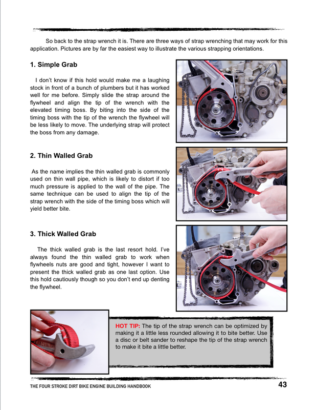
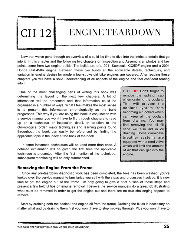
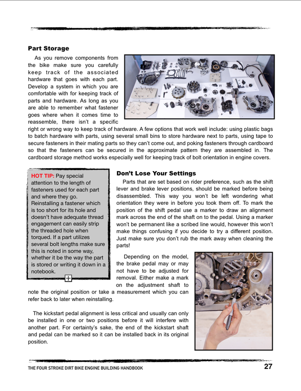
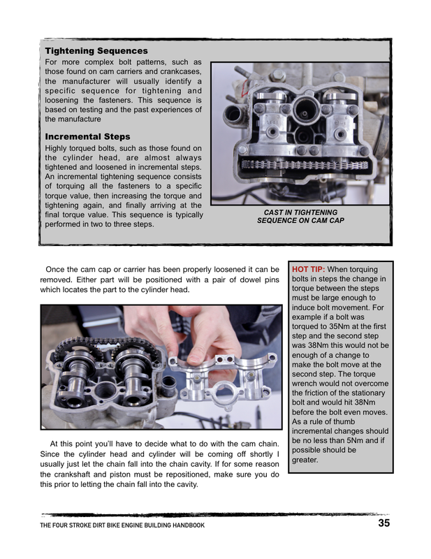
Writing this book has been such a blast and I know you will benefit from its immense value if you are planning a rebuild. Here are a few pages from the book to give you a sneak peak on the massive amount of technical content provided for dirt bike engine building enthusiasts.
As we wrap up this final post on precision measuring from my Engine Building Series, I would love to take a moment and tell you a little bit about the book I just published, The Four Stroke Dirt Bike Engine Building Handbook. As someone who has been following the DIY Moto Fix Engine Building Series posts, I think you're going to love the in-depth knowledge and information provided in this book on dirt bike engine building.
The Four Stroke Dirt Bike Engine Building Handbook provides incredible insight on the process of building a four stroke dirt bike engine. I wanted to bring at-home mechanics the level of expertise present in the industry when it comes to engine building, and do it in a way that is accessible and easy to understand.
This book is presented in a format that helps both beginners and experts. I not only write about the correct way to rebuild your engine, but also present the technical reasons why things are done the way they are in the engine building world. In addition, I supply information not found in service manuals for building high performance racing engines. Reading this book will also prevent you from making crucial mistakes that many at-home mechanics unknowingly suffer from when rebuilding.
Writing this book has been such a blast and I know you will benefit from its immense value if you are planning a rebuild. Here are a few pages from the book to give you a sneak peak on the massive amount of technical content provided for dirt bike engine building enthusiasts.

The Four Stroke Dirt Bike Engine Building Handbook is available in both an eBook format and a printed and bound version. Check the book out and learn more by clicking here.
Thanks so much for your support and enthusiasm for DIY Moto Fix. Read on for my final post on utilizing the remaining six precision measuring tools.
Thanks so much for your support and enthusiasm for DIY Moto Fix. Read on for my final post on utilizing the remaining six precision measuring tools.
Plastigauge
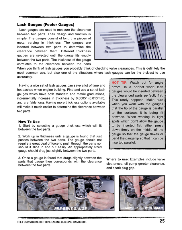
Plastigauge is one of the only measurement tools you won’t mind throwing away once you are done using it. Plastigauge is a measurement tool used to check the clearance between parts. The plastigauge consists of little strips of plastic which are inserted between two parts. Once assembled the plastic strip is compressed. The amount the strip compresses can be measured and correlated to a chart (supplied with the plastigauge) which defines the clearance for the measured compressed width of the strip. For engine building purposes plastigauge is ideal for checking clearances between engine components utilizing plain bearings. The plastigauge is a great tool for confirming clearance and measurements.
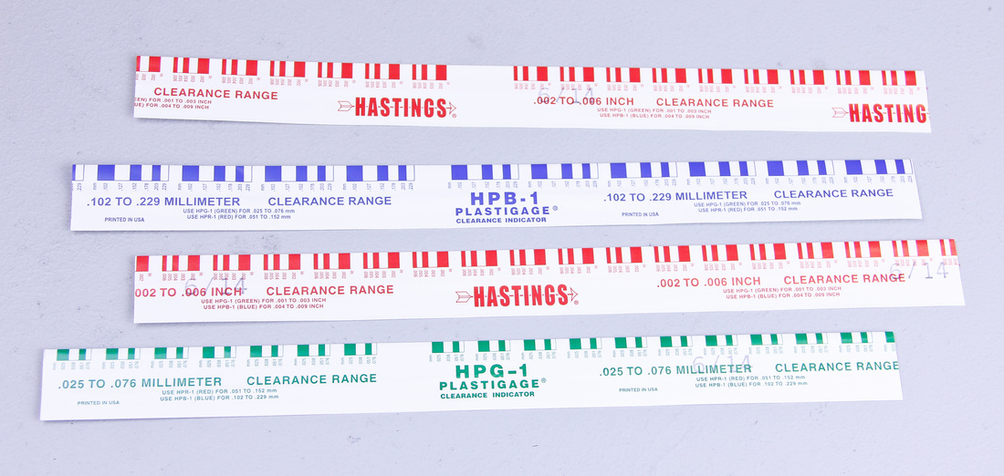
Another plus is that unlike most other measuring tools, plastigauge is cheap! Plastigauge is usually sold in an assortment of sizes which cover multiple clearance ranges. Plastigauge strips will come in different diameters and each diameter will be capable of measuring a certain clearance range.
Where to Use: Examples include cam to cam journal clearance, crank bearing to crankshaft journal clearance, and crank pin to rod bearing clearance.
Calibrating Plastigauge
Finally a measurement tool where no calibration is necessary. Just make sure you choose the appropriate size strip for your application. Also make sure the plastigauge is fairly new. Plastigauge does get old after awhile and using old plastigauge may not yield accurate results.
Reading Plastigauge
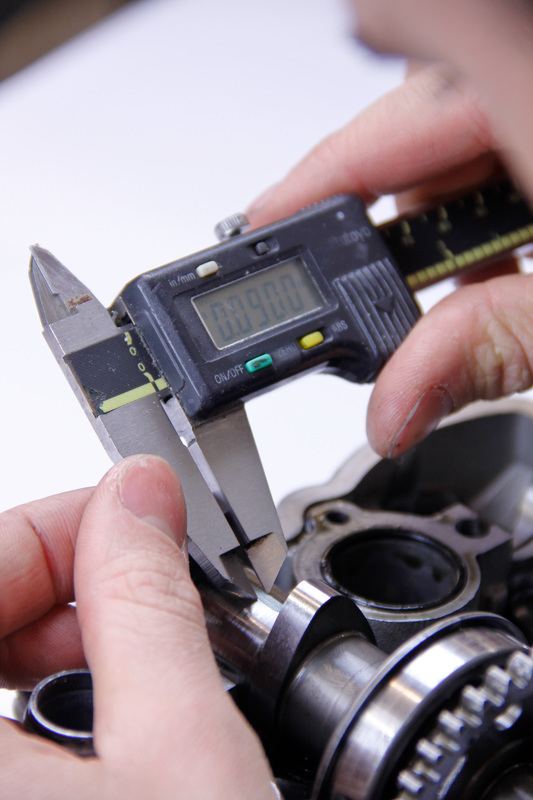
1. After the plastigauge has been compressed use a calipers to measure the width of the compressed strip.
Where to Use: Examples include cam to cam journal clearance, crank bearing to crankshaft journal clearance, and crank pin to rod bearing clearance.
Calibrating Plastigauge
Finally a measurement tool where no calibration is necessary. Just make sure you choose the appropriate size strip for your application. Also make sure the plastigauge is fairly new. Plastigauge does get old after awhile and using old plastigauge may not yield accurate results.
Reading Plastigauge
1. After the plastigauge has been compressed use a calipers to measure the width of the compressed strip.
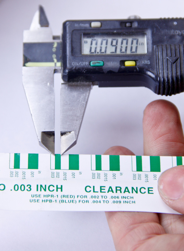
2. Record the width. Then look at the clearance chart provided with the plastigauge to determine the clearance that corresponds to the measured width.
3. Yes, it really is that simple.
How-To Use
1. Clean the parts being assembled
2. Insert a small strip of plastigauge between the parts being assembled.
How-To Use
1. Clean the parts being assembled
2. Insert a small strip of plastigauge between the parts being assembled.

3. Carefully lower the mating part down onto the plastigauge. Take great care to lower the part straight down so the plastigauge doesn’t move.
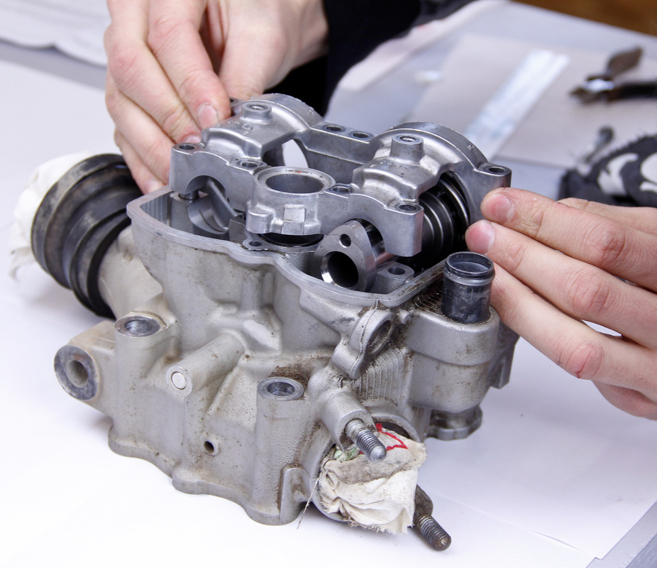
4. Install the fasteners used to secure the parts together.
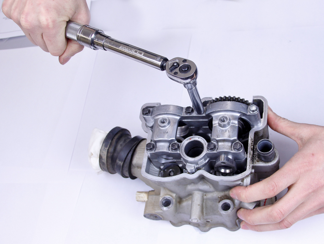
5. Tighten the fasteners to the torque value recommended by the manufacturer. Follow any special tightening patterns that may apply.
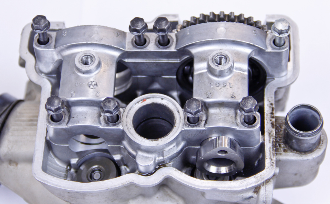
6. Carefully loosen the mated parts. Again, follow any special instructions for loosening provided by the manufacturer.
7. Remove the part. Check to see which part, if any, the plastigauge has stuck to.
8. Use a calipers to carefully measure the width of the plastigauge
8. Use a calipers to carefully measure the width of the plastigauge
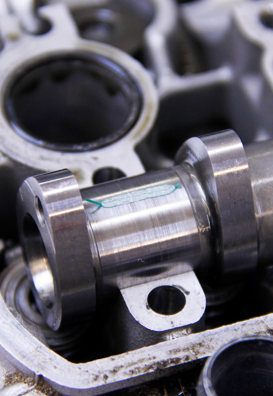
9. Refer to the chart provided with the plastigauge to determine the clearance which corresponds to the measured strip width.
Hot Tip: With a keen eye taper and out-of-roundness can also be spotted by using plastigauge. Keep an eye out for variations in strip width after it has been compressed for clues about the condition of the bore.
Hot Tip: With a keen eye taper and out-of-roundness can also be spotted by using plastigauge. Keep an eye out for variations in strip width after it has been compressed for clues about the condition of the bore.
Dial Indicator
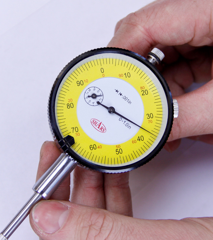
A dial indicator measures variations in height by utilizing a plunger which travels up and down. As the plunger travels a dial gauge records the amount the plunger has moved. For engine building purposes a dial indicator is a handy tool to have when measuring valve lift and finding top dead center.
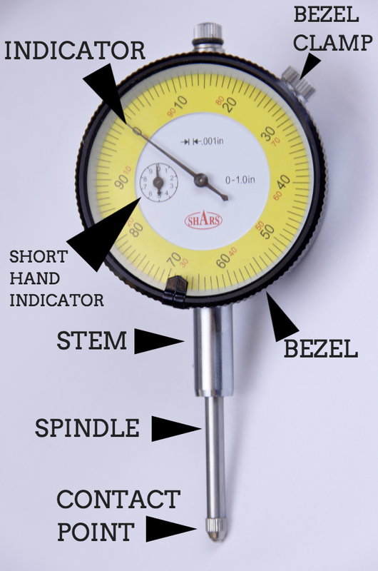
There are a wide range of dial indicators on the market. Choosing the best one for engine building may be daunting if you’re not familiar with them. There are two main features you want to look for when selecting an indicator. The amount of travel the indicator has and the resolution of the indicator. Choose an indicator with around 1.0” (25mm) of travel which has a resolution of 0.001” (0.025mm). This type of indicator will work well for engine applications.
In addition to the indicator getting a few accessories for the indicator will be beneficial. Most indicators are not sold with a base. Magnetic bases are really handy when setting the indicator up and provide a means of securing the indicator so it can’t move. Even when working with aluminum parts (ex. cylinder head) a magnetic base can be utilized by bolting a flat piece of steel to the aluminum part.
Dial indicators usually come equipped with rounded contact points which are ideal for measuring flat surfaces. Occasionally you may encounter a setup which requires a different contact point. A variety of contact points are offered for indicators and having an assortment never hurts.
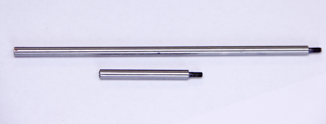
Tip extensions are a must have if you plan on doing any deep depth work with the indicator. One situation which routinely requires a tip extension is when using the indicator to find top dead center of the piston. Tip extensions can be bought in multiple lengths.
In addition to the indicator getting a few accessories for the indicator will be beneficial. Most indicators are not sold with a base. Magnetic bases are really handy when setting the indicator up and provide a means of securing the indicator so it can’t move. Even when working with aluminum parts (ex. cylinder head) a magnetic base can be utilized by bolting a flat piece of steel to the aluminum part.
Dial indicators usually come equipped with rounded contact points which are ideal for measuring flat surfaces. Occasionally you may encounter a setup which requires a different contact point. A variety of contact points are offered for indicators and having an assortment never hurts.
Tip extensions are a must have if you plan on doing any deep depth work with the indicator. One situation which routinely requires a tip extension is when using the indicator to find top dead center of the piston. Tip extensions can be bought in multiple lengths.
Where To Use: Examples include measuring valve lift, and finding top dead center.
Reading Dial Indicators
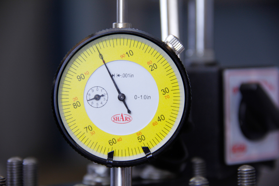
Reading a dial indicator is very similar to reading a dial calipers. The only difference is the dial indicator’s gauge face is equipped with a second smaller dial face. For an indicator with a resolution of 0.001” the small face is divided into 10 graduations. Each graduation represents a tenth of an inch. The outer dial face is divided into thousandths of an inch. Each time the outer needle rotates one revolution around, the second small needle tallies a tenth of an inch. This eliminates the need for the user to keep track of how many times the needle has gone around.
Reading Dial Indicators
Reading a dial indicator is very similar to reading a dial calipers. The only difference is the dial indicator’s gauge face is equipped with a second smaller dial face. For an indicator with a resolution of 0.001” the small face is divided into 10 graduations. Each graduation represents a tenth of an inch. The outer dial face is divided into thousandths of an inch. Each time the outer needle rotates one revolution around, the second small needle tallies a tenth of an inch. This eliminates the need for the user to keep track of how many times the needle has gone around.
The total measurement is comprised of the number of tenths of an inch the smaller needle is indicating plus the number of thousandths the large needle is indicating. In the picture above the dial indicator reads 0.136".
For metric and other resolutions of dial indicators the reading process is identical to the above. Take note of the units and resolution and proceed to read the indicator accordingly.
Calibrating Dial Indicators
Checking and adjusting the accuracy of dial indicators usually can’t be done easily in one’s own shop. For dial indicator calibration the indicator would have to be sent to a calibration lab. Fortunately, the applications an indicator is used for when building engines doesn’t require the utmost accuracy so calibration is seldom a problem.
How To Use
1. Clean the contact point of the indicator and the part which will be indicated.
2. Carefully set the indicator up so that it is fixed to a sturdy base which can’t move.
3. The amount of travel in each direction you will need depends on the specific application you are measuring. Consider the motion and travel of the part you want to measure and set the indicator accordingly so that it doesn’t run out of travel halfway through measuring. For example, when measuring valve lift you would want to engage the indicator so that around a quarter of the plungers travel has been used.
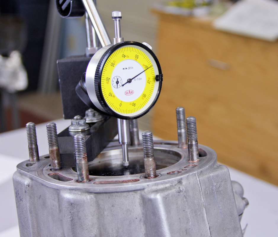
4. Square the spindle of the indicator being measured. The more square the indicator spindle is to the part the more accurate the readings will be. If the indicator is set at an angle to the direction of travel of the part the indicator will not read accurately. Keep this in mind and always try to set the indicator spindle as square as possible to the part being measured.
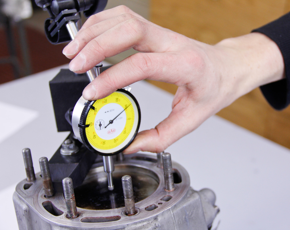
5. Zero the indicator by rotating the gauge face so the outer needle aligns with “0”. For example when measuring valve lift the zero point would be when the valve is fully closed. When checking runout the zero point may be a low or high point.
6. Move the part being indicated a few times returning it to its starting position each time. Check to make sure the indicator consistently reads “0”. If it doesn’t then carefully adjust the gauge face to realign the needle.
7. Once the indicator has been zeroed proceed to move the part being indicated and take measurements.
8. After measuring return the part to its original position. Occasionally an indicator can get bumped or something can happen during the procedure. This is a good way to confirm one last time that the indicator is still zeroed.
Dial Test Indicators
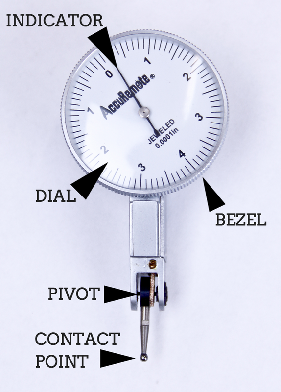
Dial test indicators are very similar to dial indicators, however their primary function is more as a comparative tool than a measurement tool. The main difference between a dial indicator and dial test indicator is the dial test indicator uses a contact point which pivots instead of a plunger that travels up and down. This pivoting action results in an arcing path instead of a straight up and down path. The test indicator is best suited for taking comparative measurements and zeroing runout. For engine building purposes this makes a pair of dial test indicators well suited for measuring the runout of a crankshaft.
Just like dial indicators, test indicators are made with different lengths of travel and different resolutions. The most suitable resolution for crankshaft truing and inspection purposes is 0.0001” (0.0025mm). Most test indicators with a resolution of 0.0001” will have a travel of 0.008” (0.203mm) or 0.010” (0.254mm) which will be suitable for crankshaft inspection.
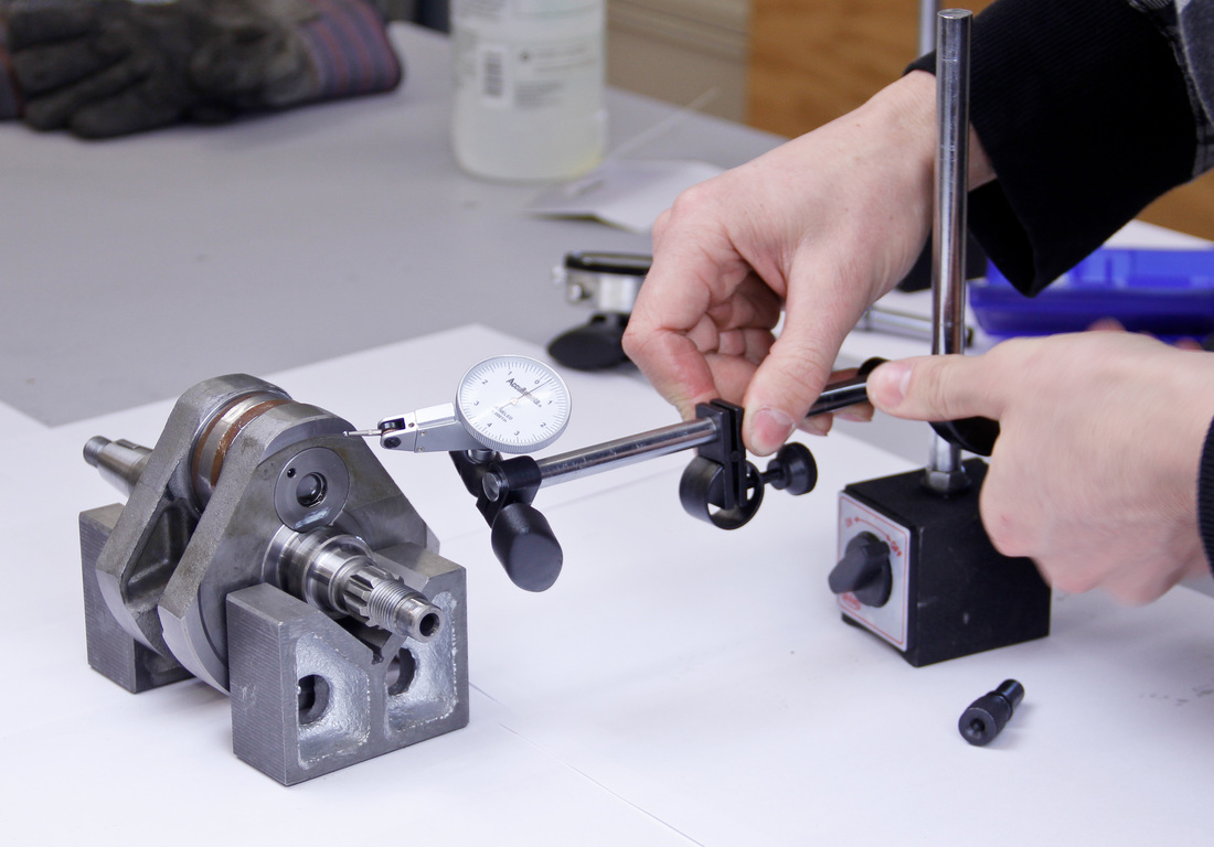
The test indicators will require fixturing so having a pair of bases, stands, and clamps is necessary. Fortunately, the test indicators use similar mounting systems as dial indicators so if you have fixturing for dial indicators you are all set to mount the test indicators.
Where To Use: Examples include crankshaft inspecting or truing.
Reading Dial Test Indicators
The gauge face of a dial test indicator is symmetrical. The face is divided into graduations based on the resolution of the test indicator. Each side of the face represents half of the total travel of the test indicator. Reading the gauge is simply a matter of determining how many graduations the needle has moved from its starting point to its ending point.
Calibrating Dial Test Indicators
Like dial indicators, calibrating dial test indicators is usually done by a professional calibration lab. As long as the test indicator is well cared for the need for calibration should be infrequent.
How To Use
Since the contact point of the test indicator travels in an arc the way the indicator is set up has an impact on measurement. This is the main reason test indicators can’t be relied on heavily for taking measurements and instead are used for comparing.
1. Clean the contact point of the indicator and the part which will be indicated.
2. Carefully set the indicator up so that it is fixed to a sturdy base which cannot move.
3. Most test indicators function best when the contact point is perpendicular to the direction of travel of the workpiece. Some indicators differ slightly and should be set at a slight angle, so confirm with the instructions supplied with your test indicator to attain the correct orientation.
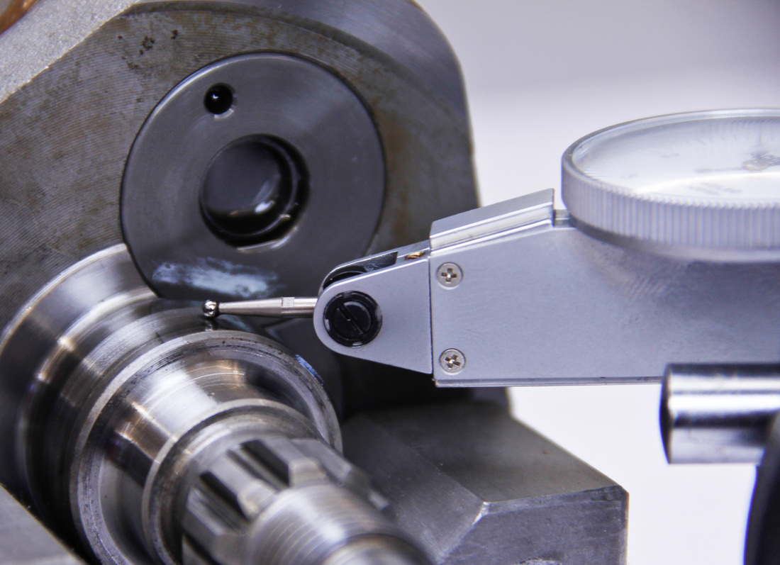
4. The majority of test indicators work best when the contact point is preloaded. As a rule of thumb a 1/10 - ¼ revolution of the needle is about right for setting preload. Instructions supplied with individual indicators may have specific preload instructions.
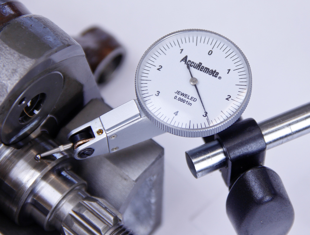
5. Rotate the part to find the high or low point. Zero the indicator by rotating the dial face so the needle aligns with “0”.
6. Move the part being indicated a few times returning it to its starting position each time. Check to make sure the indicator consistently reads “0”. If it doesn’t then carefully adjust the gauge face to realign the needle.
7. Once the indicator has been zeroed proceed to move the part being indicated and take measurements.
8. After measuring return the part to its original position. Occasionally an indicator can get bumped or something can happen during the procedure and this is a good way to confirm one last time that the indicator is still zeroed.
Transfer Gauges
Transfer gauges are measurement tools which don’t yield a direct measurement. They are simply tools which can be used to transfer the dimensions of something requiring measurement to a measurement tool. There are two types of transfer measurement tools commonly used in engine building, small hole gauges and telescoping gauges.
 |  |
Transfer gauges can be tricky to use accurately for a couple reasons. First, they introduce a second source for error. Instead of taking a direct measurement the measured part must first be sized using a transfer gauge. Then the gauge must be measured by a measurement tool such as a micrometer. It is easy to see how mistakes can accrue in this situation. Second, transfer gauges rely heavily on feel to obtain accurate measurements. If the user of the gauge is unskilled, the transfer measurements could be all over the board.
Taking these points into consideration transfer gauges can still be incredibly helpful when measuring engine parts. Transfer gauges are one of the most relied on methods of accurately measuring internal diameters.
Taking these points into consideration transfer gauges can still be incredibly helpful when measuring engine parts. Transfer gauges are one of the most relied on methods of accurately measuring internal diameters.
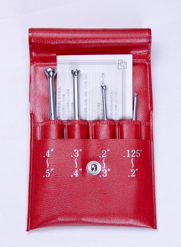
Small Hole Gauges
Small hole gauges are used to transfer internal measurements usually less than ½” in diameter.
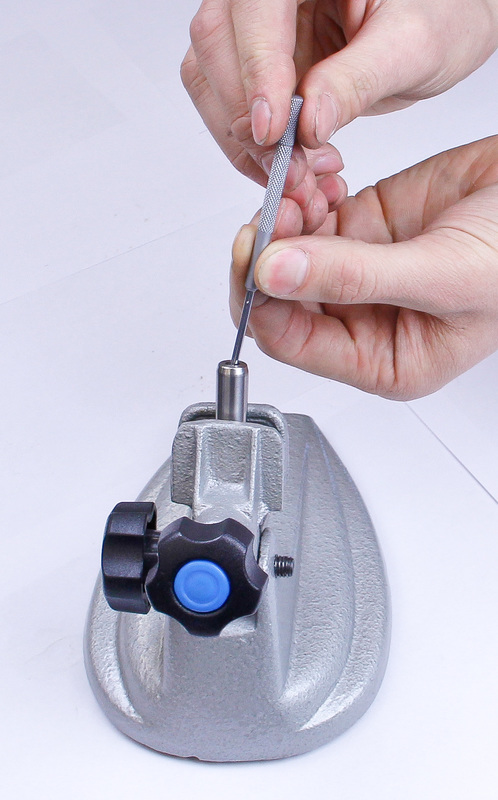
A small hole gauge has a split in its head which allows the head to expand or contract to the size of the part being measured. An adjustment knob at the end of the handle is turned to expand or contract the head. The head on the gauge can either be a full or half sphere design. The half sphere designs have the advantage of being able to measure blind holes.
Small hole gauges are usually sold in sets capable of measuring from around 0.125 - 0.500” (3.175 - 12.4mm). Each set is comprised of around four gauges with each gauge being able to measure a certain portion of the set’s total range. For engine building purposes, small hole gauges are primarily used to measure the inner diameters of valve guides.
Where To Use: Valve guides
How to use
1. Clean the bore of the part to be measured and the head of the small hole gauge.
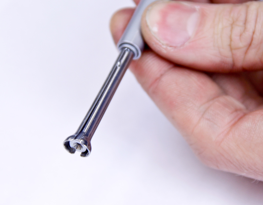
2. Slowly turn the adjustment knob on the gauge expanding the head of the gauge inside the bore of the part being measured.
3. Simultaneously, gently rock the gauge back and forth and fore and aft inside the bore until the head of the gauge just starts to drag on the bore of the part. As you rock back and forth make sure the handle of the gauge passes through the point where the handle is square to the bore.
 |  |
4. Remove the gauge.
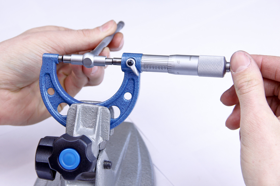
5. Use a micrometer to measure the diameter of the gauge to determine the diameter of the part’s bore. Since the gauge can easily be compressed little to no pressure can be applied by the measuring faces of the micrometer.
5. Use a micrometer to measure the diameter of the gauge to determine the diameter of the part’s bore. Since the gauge can easily be compressed little to no pressure can be applied by the measuring faces of the micrometer.
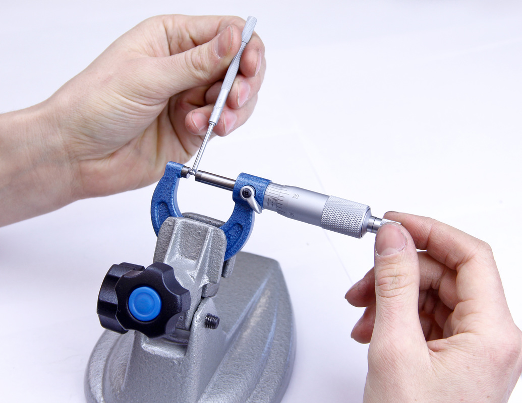
6. Slide the gauge back and forth and fore and aft as you delicately tighten the ratchet or thimble of the micrometer. An accurate reading will be obtained when the micrometer just starts to drag against the gauge. Remember to measure perpendicular to the split in the gauge.
7. Lock the the spindle of the micrometer and read the micrometer to obtain the bore diameter.
Hot Tip: Since this is partly an exercise of feel, take multiple measurements until the measurements start to yield the same results. This way you can be certain the measurements are accurate.
Hot Tip: Since this is partly an exercise of feel, take multiple measurements until the measurements start to yield the same results. This way you can be certain the measurements are accurate.
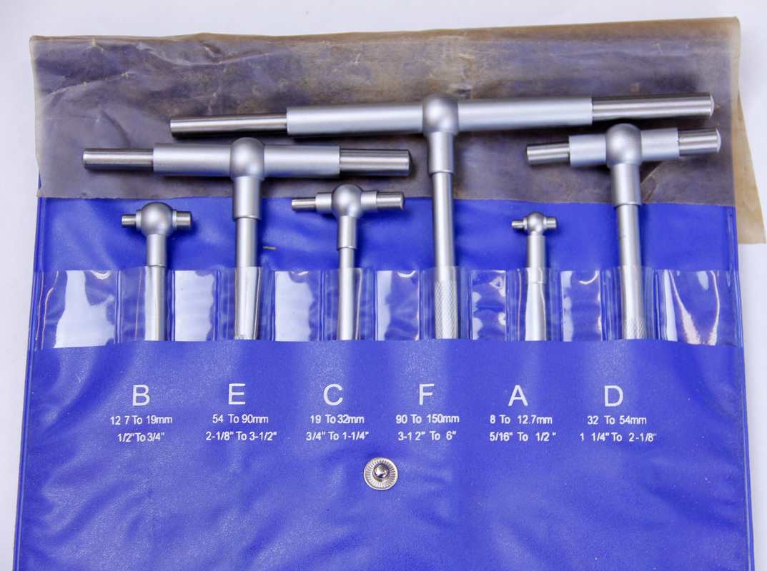
Telescoping Gauges
Telescoping gauges are the big brothers of the small hole bore gauges. Telescoping gauges are shaped like a “T”. A tightening knob is situated at the handle end and it controls one or two spring loaded plungers (dependent on gauge type). Once the knob is loosened the plunger(s) expand outwards to capture the diameter of the bore being measured. The plunger ends are convex so the gauge can be rocked back forth to obtain the measurement.
Telescoping gauges are usually sold in sets capable of measuring from around 0.3125 - 6.0” (8 - 152.4mm). Each set is comprised of around six gauges with each gauge being able to measure a certain portion of the set’s total range.
Where To Use: Examples include lifter bucket bore and cylinder bore.
How to use
1. Clean the bore of the part to be measured and the ends of the plungers on the telescoping gauge.
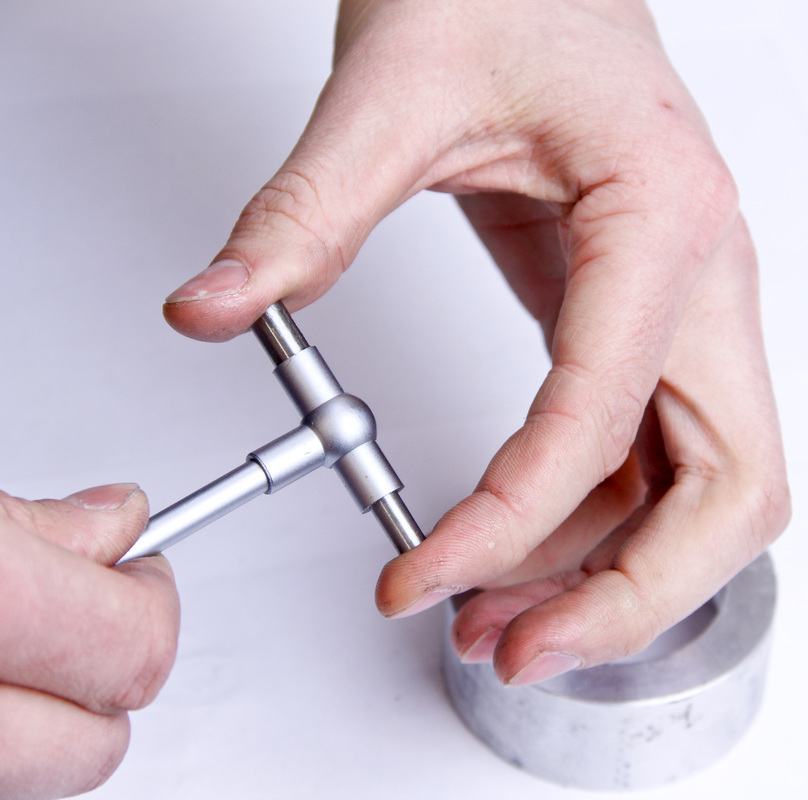
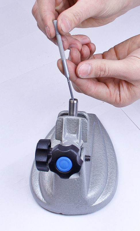
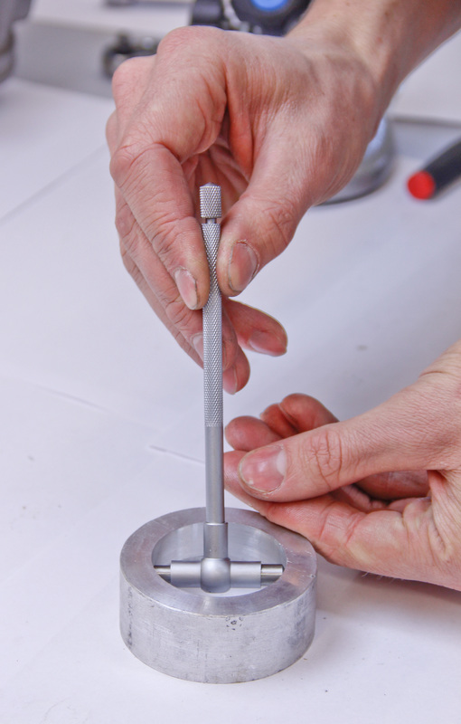
2. Set the gauge inside the bore with one plunger touching the side of the bore.
3. Slowly loosen the adjustment knob on the gauge handle expanding the plungers of the gauge inside the bore of the part being measured.
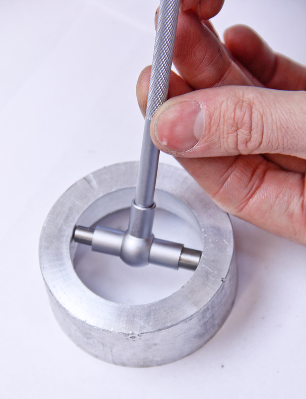
4. Set the gauge up so that the handle is just out of square with the bore.
5. Tighten the adjustment knob down.
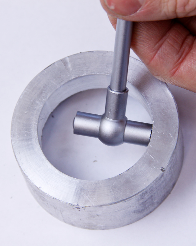
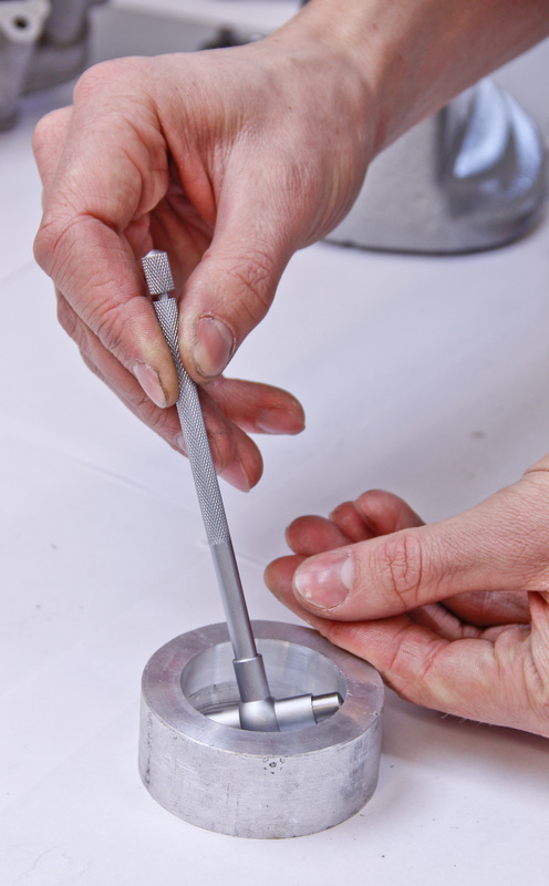
6. Gently wiggle the gauge back and forth while passing the gauge through the bore. Only pass the gauge through the bore once. This will center the gauge and set the plungers to the diameter of the bore.
6. Gently wiggle the gauge back and forth while passing the gauge through the bore. Only pass the gauge through the bore once. This will center the gauge and set the plungers to the diameter of the bore.
 |  | 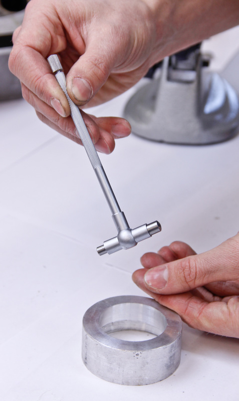 |
7. Clean both measuring faces.
8. Use a micrometer to measure the diameter of the gauge to determine the diameter of the part’s bore. Since the gauge can be compressed, little to no pressure can be applied by the measuring faces of the micrometer.
8. Use a micrometer to measure the diameter of the gauge to determine the diameter of the part’s bore. Since the gauge can be compressed, little to no pressure can be applied by the measuring faces of the micrometer.
9. Slide the gauge back and forth and fore and aft as you delicately tighten the ratchet or thimble of the micrometer. An accurate reading will be obtained when the micrometer just starts to drag against the gauge.
10. Lock the the spindle of the micrometer and read the micrometer to obtain the bore diameter.
Hot Tip: Since this is partly an exercise of feel, take multiple measurements until the measurements start to yield the same results. This way you can be certain the measurements are accurate.
Hot Tip: Since this is partly an exercise of feel, take multiple measurements until the measurements start to yield the same results. This way you can be certain the measurements are accurate.
V-Blocks
A V-block is a large precision machined metal block with a V in it. During an engine build V-blocks are used primarily for checking runout of cylindrical parts such as the crankshaft.
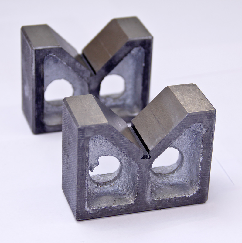
When shopping for V-blocks a precision ground matched set should be purchased. Fancy versions may come with magnetic bases, multiple Vs, clamps, or rollers. While some of these features are nice they certainly aren’t necessary and add to the cost.
That concludes my three part series on precision measuring for the at-home mechanic, pretty intricate stuff right? I always joke that I could write a book on precision measuring, and then I went and did it! Well, I at least devoted an entire chapter to its intricacies and utilization when building engines in The Four Stroke Dirt Bike Engine Building Handbook.
Click here to order the eBook version online. When purchasing be sure to enter the discount code: holeshot2015 to receive 25% off. The book will be sent right to your email address where you can either view it online or download it to your mobile phone or computer.
Sounds pretty great right? I hope you love it because we spent the last three months working hard on it to make it the number one resource for at-home dirt bike mechanics. Have a great weekend!