How To Use Measurement Tools
It’s finally time! Hopefully from last week’s post you are beginning to feel like you have an understanding of the world of measuring and are ready to start working with the tools. In this post I will be covering four of the ten types of measuring tools you are most likely to encounter when rebuilding a dirt bike engine. Next week I will cover the remaining six tools.
Each measurement tool in this post features a description of appropriate applications for the tool and a step-by-step tutorial on how to use it.
If you want all this info in one place, we compiled all three posts into a free downloadable guide for you. Click to download your copy of The At-Home Mechanic's Guide To Precision Measurement. This guide is designed as a reference so that you can easily come back to it at any time as you become more comfortable using measurement tools during a rebuild.
As I mentioned in last week’s post, make sure your measurement tools are at room temperature prior to measuring. If you brought your tools from a warmer or colder room they will need time to adjust to the temperature...
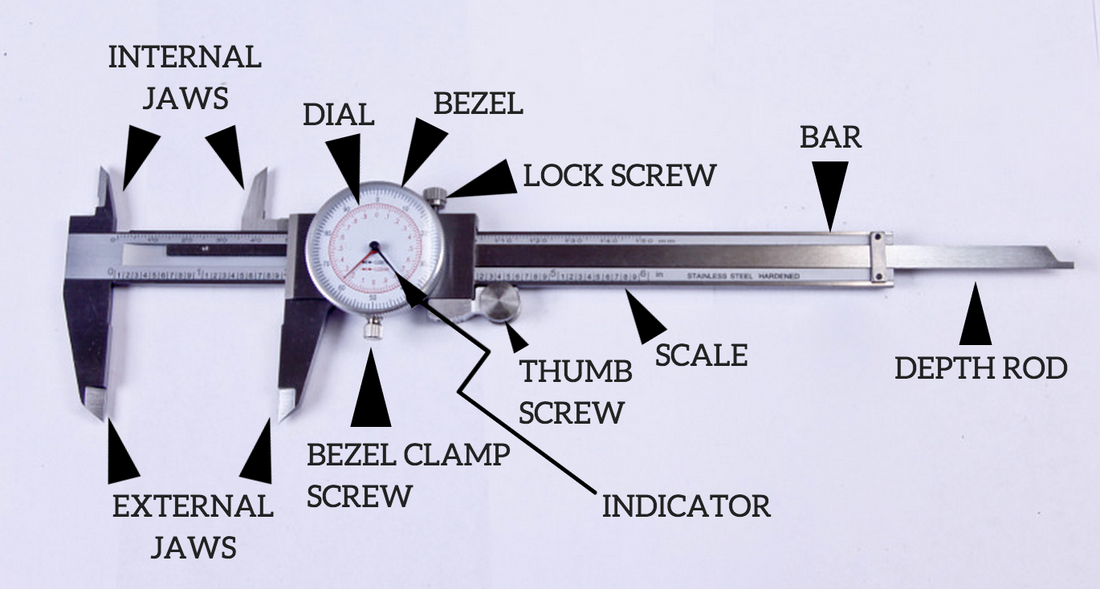
Calipers : Digital And Dial
Calipers are one of the most versatile measuring tools due to their ability to take internal, external, and depth measurements. Calipers are also able to take some of the widest ranges of measurements. Most calipers have a measurement range from 0 - 6 inches (0 - 150mm). For these reasons every engine builder should have a caliper at their disposal. Calipers can come with dial, digital, or Vernier scale readouts. Personally I would avoid the Vernier type as they are cumbersome to read, instead choose either a digital or dial caliper.
Where to use: Some examples include valve spring lengths, clutch disc thickness, and cam lobes. Calipers are not the most accurate measuring tool and should not be used where extreme accuracy is required. Most calipers have an accuracy of about 0.001” (0.025mm).
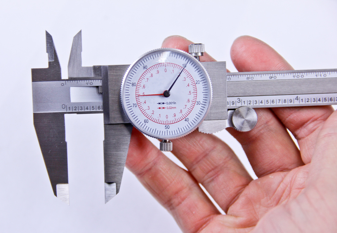
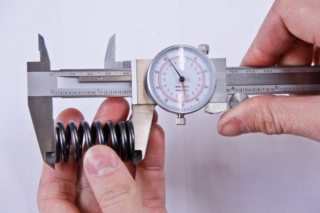
Reading A Dial Caliper: A dial caliper consists of a scale which runs along the bar of the caliper. Depending on the type of caliper you have, the scale will either be inch or metric based. On an inch caliper the scale will be in tenths of an inch while a metric scale will be in millimeters. To read the scale simply line up the edge of the jaw with the closest whole value. Once the whole value has been found move to the dial. The dial will be broken into thousandths of an inch or hundredths of a millimeter. Simply add the value indicated by the pointer on the dial to the value previously recorded on the scale. In the photo below the caliper incorporates both inch and metric scales. The caliper reads 0.610" (15.49mm).
Reading A Dial Caliper: A dial caliper consists of a scale which runs along the bar of the caliper. Depending on the type of caliper you have, the scale will either be inch or metric based. On an inch caliper the scale will be in tenths of an inch while a metric scale will be in millimeters. To read the scale simply line up the edge of the jaw with the closest whole value. Once the whole value has been found move to the dial. The dial will be broken into thousandths of an inch or hundredths of a millimeter. Simply add the value indicated by the pointer on the dial to the value previously recorded on the scale. In the photo below the caliper incorporates both inch and metric scales. The caliper reads 0.610" (15.49mm).
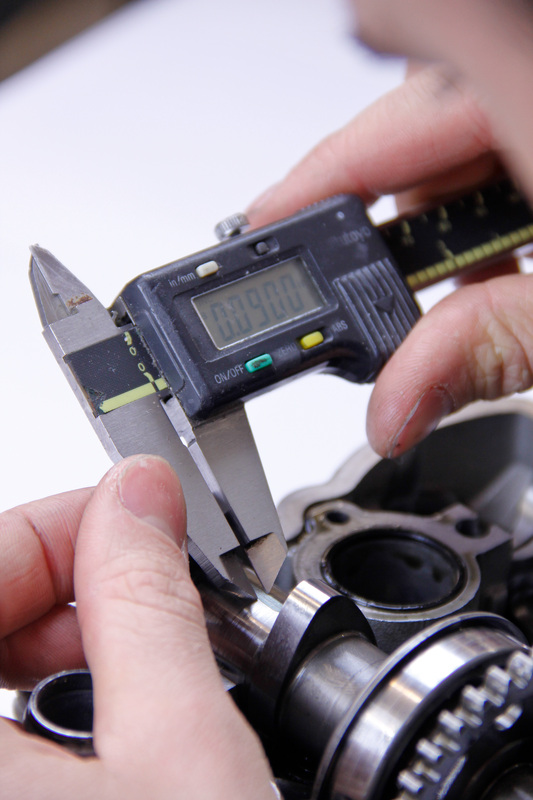
Reading A Digital Caliper: The value shown on the digital readout is the total value. Most digital calipers have a button which can be pressed to cycle between inch and metric units.
Calibration For External and Internal Measurements Using A Caliper
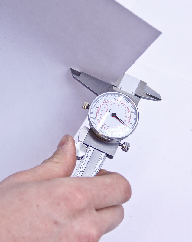
1. Start by ensuring the jaws are free of dirt or debris. Clamp a piece of paper between the jaws and slide the jaws past the paper.
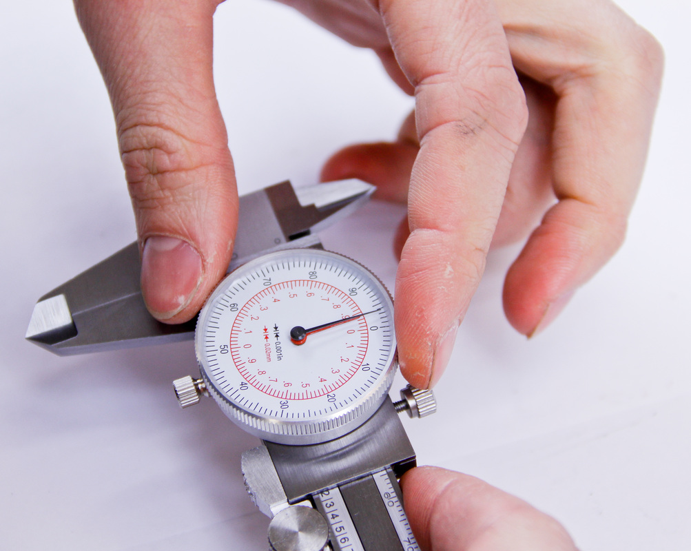
2. Close the jaws completely. On a digital caliper simply press the “zero” button to zero the caliper. On a dial caliper loosen the bezel clamp and rotate the dial face so that the “0” aligns with the pointer.
1. Start by ensuring the jaws are free of dirt or debris. Clamp a piece of paper between the jaws and slide the jaws past the paper.
2. Close the jaws completely. On a digital caliper simply press the “zero” button to zero the caliper. On a dial caliper loosen the bezel clamp and rotate the dial face so that the “0” aligns with the pointer.
|
|
3. Slide the caliper open and closed a few times to confirm the caliper consistently reads “0”. If for some reason the caliper does not repeatedly read "0" try re-calibrating the caliper.
How To Use - External Measurements
1. Position the part to be measured between the jaws as close to the bar of the caliper as possible. The further out the part sits in the jaws the more likely the jaws are to flex, resulting in a less accurate reading.
How To Use - External Measurements
1. Position the part to be measured between the jaws as close to the bar of the caliper as possible. The further out the part sits in the jaws the more likely the jaws are to flex, resulting in a less accurate reading.
2. Make sure the part sits squarely in the jaws of the caliper.
3. Apply a moderate amount of pressure to the outer jaw. This is one of those Goldilocks situations where it can’t be too loose or too tight. Too loose to the point where the part can fall out of the jaws will result in an oversized reading. Too tight to the point the jaws start to flex will result in an undersized reading. Acquiring the feel to determine the correct pressure to put on the jaws will come with practice.
4. Once finished measuring, return the jaws back to zero and make sure the caliper zeros.
5. For situations where utmost accuracy is required, take a few measurements to confirm repeatability.
How To Use - Internal Measurements
The process for obtaining good reliable internal measurements is the same as that of the external measurements. Simply utilize the internal jaws when measuring. Remember to make sure the jaws sit squarely in the bore as you measure and to keep a moderate amount of pressure on the part.
Calibration For Depth Measurements
|
|
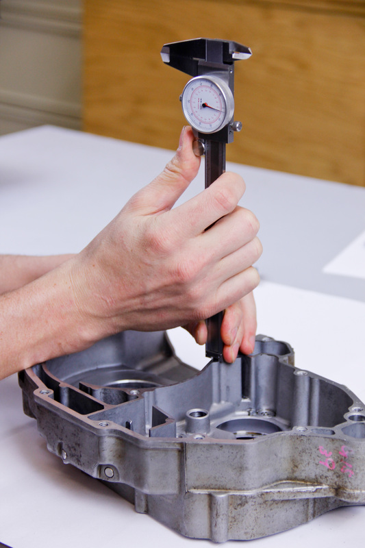
1. Extend the depth rod out from the end of the caliper.
2. Slowly lower the end of the caliper down retracting the depth rod until the end of the caliper sits flush with the flat surface. Make sure to keep the end of the caliper square to the surface as it is lowered.
3. Once the end of the caliper is sitting flush with the flat surface zero the dial.
4. Extend and contract the depth rod a few times against the flat surface making sure the dial zeros each time.
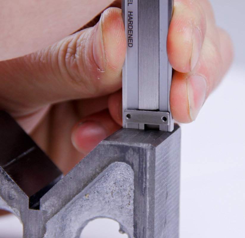
How to Use - Depth Measurements
1. Square the end of the caliper up against the surface the depth measurement will be taken from.
2. Slowly lower the end of the caliper down retracting the depth rod until the end of the caliper sits flush with the flat surface. Make sure to keep the end of the caliper square to the surface as it is lowered.
3. Once the end of the caliper is sitting flush with the flat surface zero the dial.
4. Extend and contract the depth rod a few times against the flat surface making sure the dial zeros each time.
How to Use - Depth Measurements
1. Square the end of the caliper up against the surface the depth measurement will be taken from.
2. Extend the depth rod down until it touches the measurement surface. Make sure the depth rod is only extended far enough so that it sits flat. Extending the rod too far and the end of the caliper may not sit flat or the depth rod could flex.
|
|
3. Confirm both the end of the caliper and depth rod are square and take the reading from the caliper.
4. Remove the caliper, stand it on end against a flat surface, and double check the depth rod still reads “0”.
Remember due to the limited surface area available for positioning the end of the caliper, having to keep them square, and the flexibility of the depth rod depth measurements are difficult to get accurate. Other measurement tools specifically designed for measuring depths accurately are much more suitable in instances where a high level of accuracy is required.
That sums up the three ways you can utilize a caliper. Remember the cleaner your caliper is the longer it will last so keep it in its case when not using it. A caliper usually ends up ruined by being dropped on the floor. A floor drop can result in the fine edges of the jaws getting nicked and damaged as well as wreaking havoc on the internals of the tool. Take care not to let them plummet to the ground.
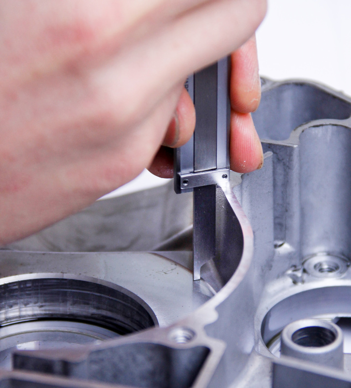
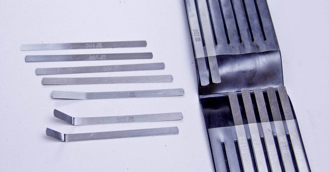
Lash Gauges (Feeler Gauges)
Lash gauges are used to measure the clearance between two parts. Their design and function is simple. The gauges consist of long thin pieces of metal varying in thickness. The gauges are inserted between two parts to determine the clearance between them. Different thickness gauges are selected until the gauge fits snugly between the two parts. The thickness of the gauge correlates to the clearance between the parts. When you think of lash gauges you probably think of checking valve clearances. This is definitely the most common use, but also one of the situations where lash gauges can be the trickiest to use accurately.
Having a nice set of lash gauges can save a lot of time and headaches when engine building. Find and use a set of lash gauges which have both standard and metric graduations, incrementally increase in thickness by 0.0005” (0.013mm), and are fairly long. Having more thickness options available will make it much easier to determine the clearance between two parts.
Having a nice set of lash gauges can save a lot of time and headaches when engine building. Find and use a set of lash gauges which have both standard and metric graduations, incrementally increase in thickness by 0.0005” (0.013mm), and are fairly long. Having more thickness options available will make it much easier to determine the clearance between two parts.
Where to use: Examples include valve clearances, oil pump gerotor clearance, and spark plug gap.
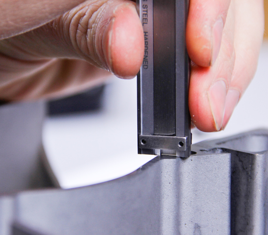
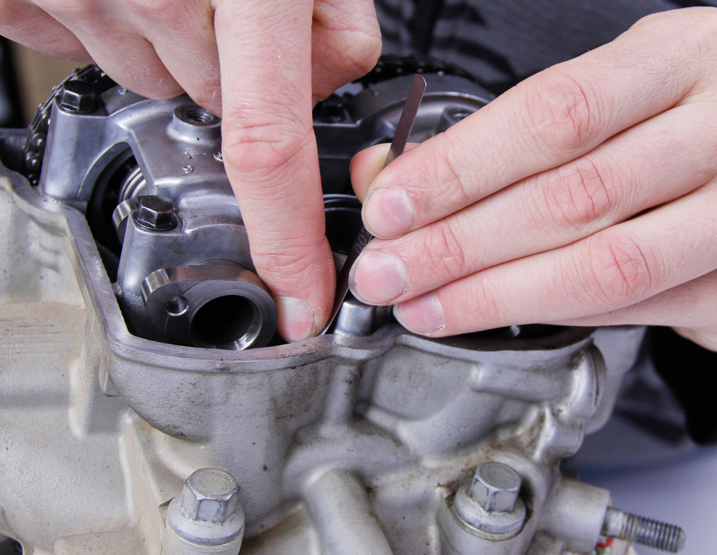
How To Use
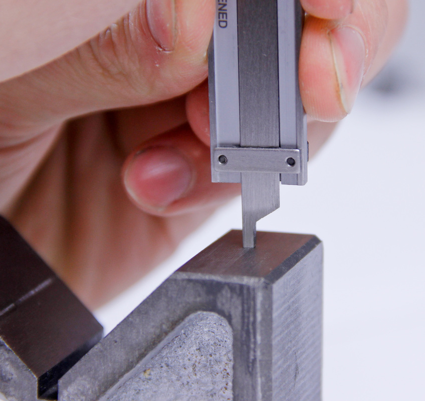
Hot Tip: Watch out for angle errors. In a perfect world lash gauges would be inserted between the clearanced parts perfectly flat. This rarely happens. Make sure when you work with the gauges that the tip of the gauge is parallel to the surfaces it is being fit between. When working in tight spots which don’t allow the gauge to be inserted flat, either press down firmly on the middle of the gauge so that the gauge flexes or bend the gauge tip so that it can be inserted parallel.
How To Use
- Start by selecting a gauge thickness which will fit between the two parts.
- Work up in thickness until a gauge is found that just passes between the two parts. The gauge should not require a great deal of force to push through the parts nor should it slide in and out easily. An appropriately sized gauge should drag just slightly between the two parts.
- Once a gauge is found that drags slightly between the parts that gauge then corresponds with the clearance between the two parts.
Hot Tip: Watch out for angle errors. In a perfect world lash gauges would be inserted between the clearanced parts perfectly flat. This rarely happens. Make sure when you work with the gauges that the tip of the gauge is parallel to the surfaces it is being fit between. When working in tight spots which don’t allow the gauge to be inserted flat, either press down firmly on the middle of the gauge so that the gauge flexes or bend the gauge tip so that it can be inserted parallel.
|
|
Outside Micrometers
During an engine build outside micrometers are the most commonly used precision measurement tool. As the name implies outside micrometers are primarily used to measure outer dimensions of parts. Both inch and metric versions of the micrometer are available with high quality inch and metric variants having resolutions of 0.0001” and 0.002mm respectively. A 0 - 6” or 0 - 150mm set is ideal and will provide an engine builder with all the micrometers needed to accurately measure dirt bike engine parts.
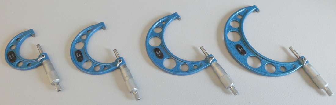
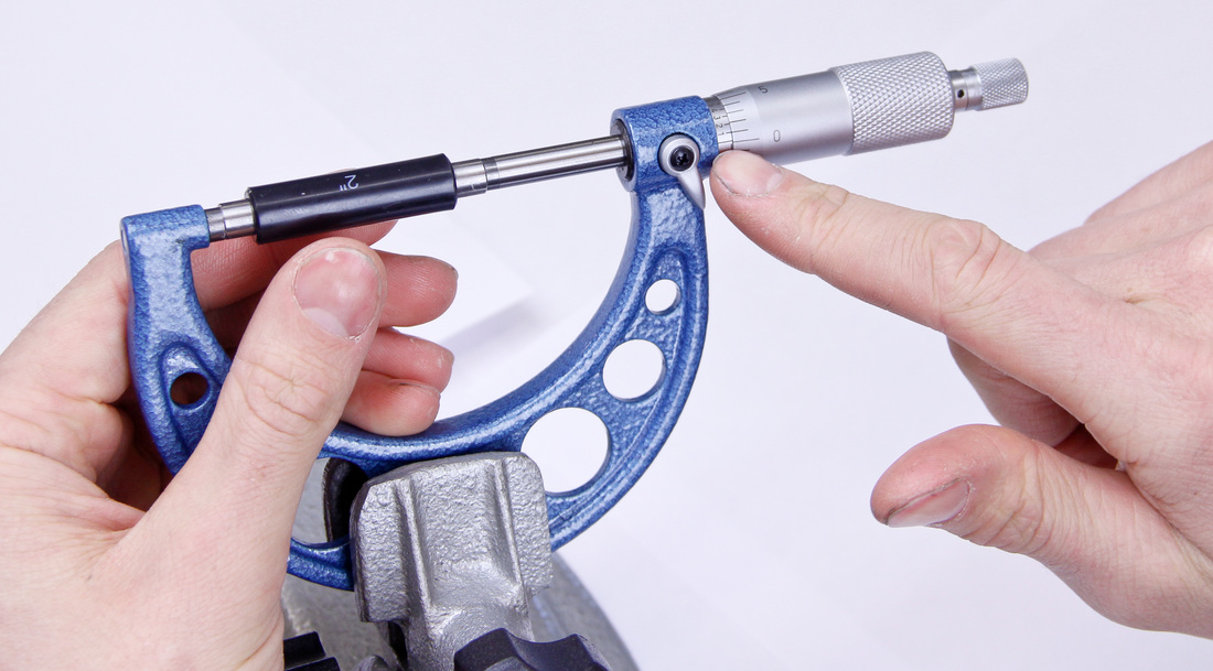
A good set of micrometers will come with their own checking standards. The checking standards are similar to gage blocks. The standards are important as they are the finely machined lengths of metal which are required to calibrate each micrometer. For a 0 - 6” set the set should come with a 1, 2, 3, 4, and 5 inch standard so each of the five micrometers which don’t close completely can be calibrated before use. In addition to the standards a good set of micrometers should come with a lock. The lock is used to clamp the spindle in place so a measurement isn’t lost before it can be read.
Micrometers are offered with or without a ratchet stop. A ratchet stop is handy for beginners because it regulates the pressure being applied to the measured part leading to more consistent readings. While used less often by seasoned professionals, I personally like the ratchet stop feature and think anyone just starting out should utilize a set with ratchet stops.
Where to use: Examples include valve stems, lifter buckets, and piston.
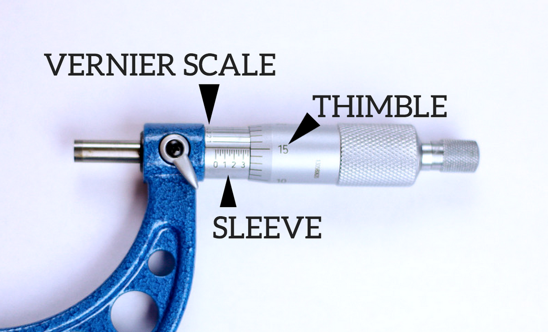
Reading Micrometers: Micrometers are easy to read as long as you understand the three parts of the measurement system found on the micrometer. The three parts of the system are the sleeve, the thimble, and the Vernier scale.
Micrometers are offered with or without a ratchet stop. A ratchet stop is handy for beginners because it regulates the pressure being applied to the measured part leading to more consistent readings. While used less often by seasoned professionals, I personally like the ratchet stop feature and think anyone just starting out should utilize a set with ratchet stops.
Where to use: Examples include valve stems, lifter buckets, and piston.
Reading Micrometers: Micrometers are easy to read as long as you understand the three parts of the measurement system found on the micrometer. The three parts of the system are the sleeve, the thimble, and the Vernier scale.
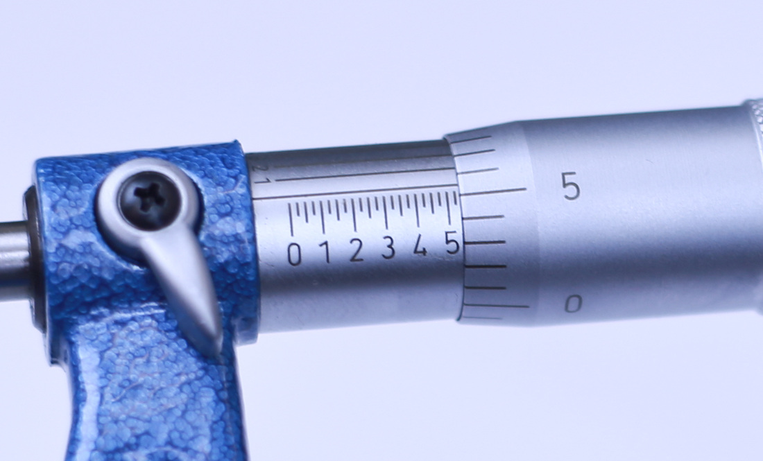
On an inch-based micrometer the sleeve features graduations of 0.025”. The sleeve of the micrometer is always read first. Keep in mind only whole fully visible lines can be counted. In the picture below the micrometer sleeve reads 0.350”.
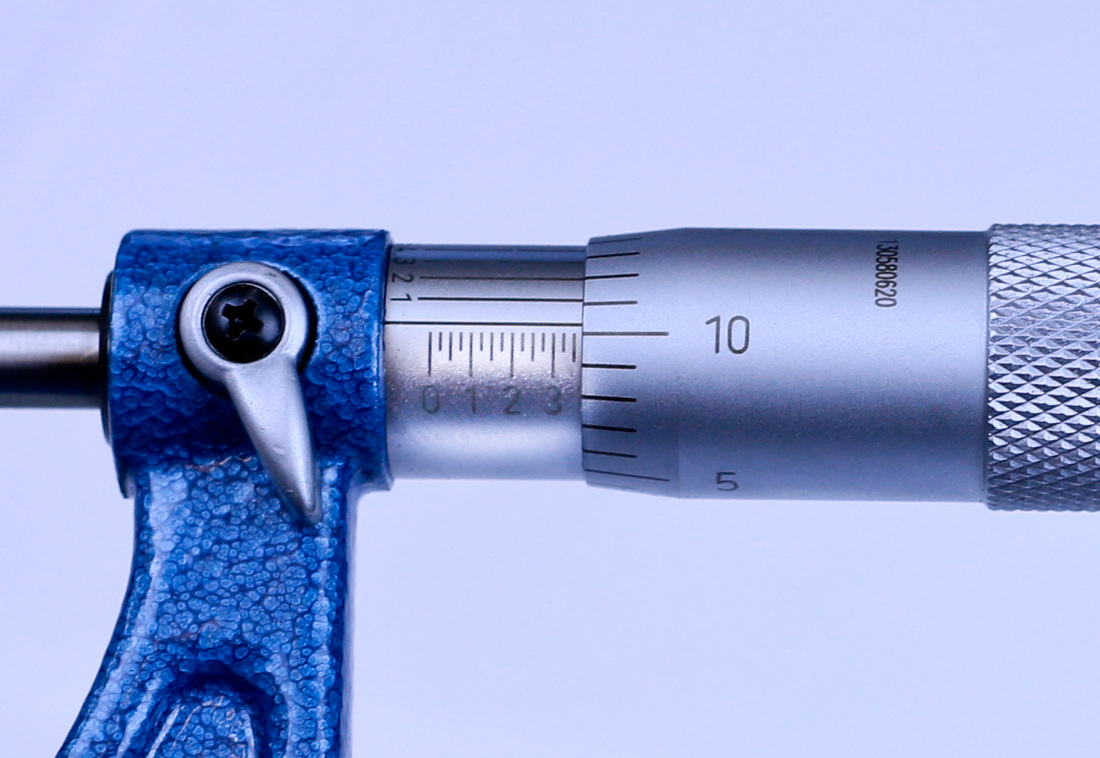
Next comes the thimble. The thimble is divided into 25 graduations of 0.001” inch increments. This makes sense because one full revolution of the spindle would be equal to one increment on the sleeve (0.025”). To determine the value on the thimble simply line up the the horizontal hash mark on the thimble with the horizontal line on the sleeve. In the picture below the thimble reads slightly more than 0.010”. The value obtained from the thimble reading is then added to the value from the sleeve, so far totaling 0.360".
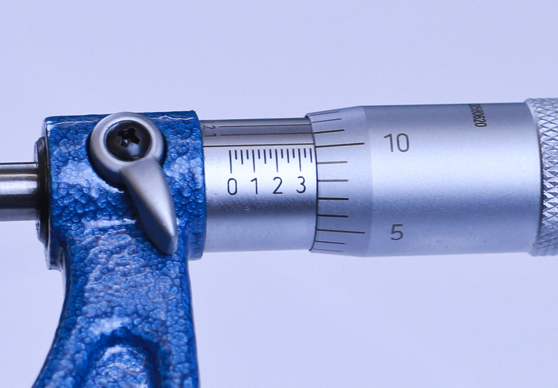
Lastly, the Vernier scale comes into play. The Vernier Scale consists of 10 horizontal lines. Each line represents 0.0001”. When all ten lines are added together the sum equals 0.001” which is equivalent to one increment on the thimble. To read the Vernier scale simply look for the set of horizontal lines that match perfectly. The corresponding value associated with the matching lines is the number of ten thousandths which must be added to sum of the sleeve and thimble value. Make sure to read the value on the Vernier scale and not on the thimble when reading the 0.0001” measurement.
In the photo below the line corresponding to the "6" on the Vernier scale matches perfectly to the line on the thimble so we know to add another 0.0006" to the measurement. The total measurement is 0.3606" (0.350" + 0.010" + 0.0006"). Unbeknownst to you, this is a 2-3 inch micrometer so 2" must be added to the measured value to arrive at a total of 2.3606".
In the photo below the line corresponding to the "6" on the Vernier scale matches perfectly to the line on the thimble so we know to add another 0.0006" to the measurement. The total measurement is 0.3606" (0.350" + 0.010" + 0.0006"). Unbeknownst to you, this is a 2-3 inch micrometer so 2" must be added to the measured value to arrive at a total of 2.3606".
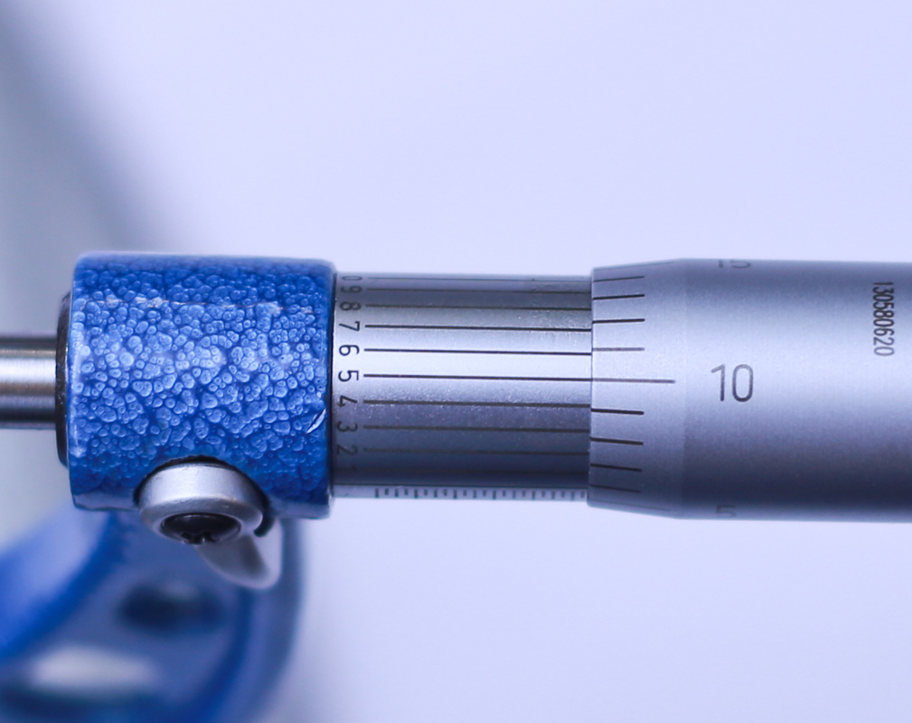
Here is another example:
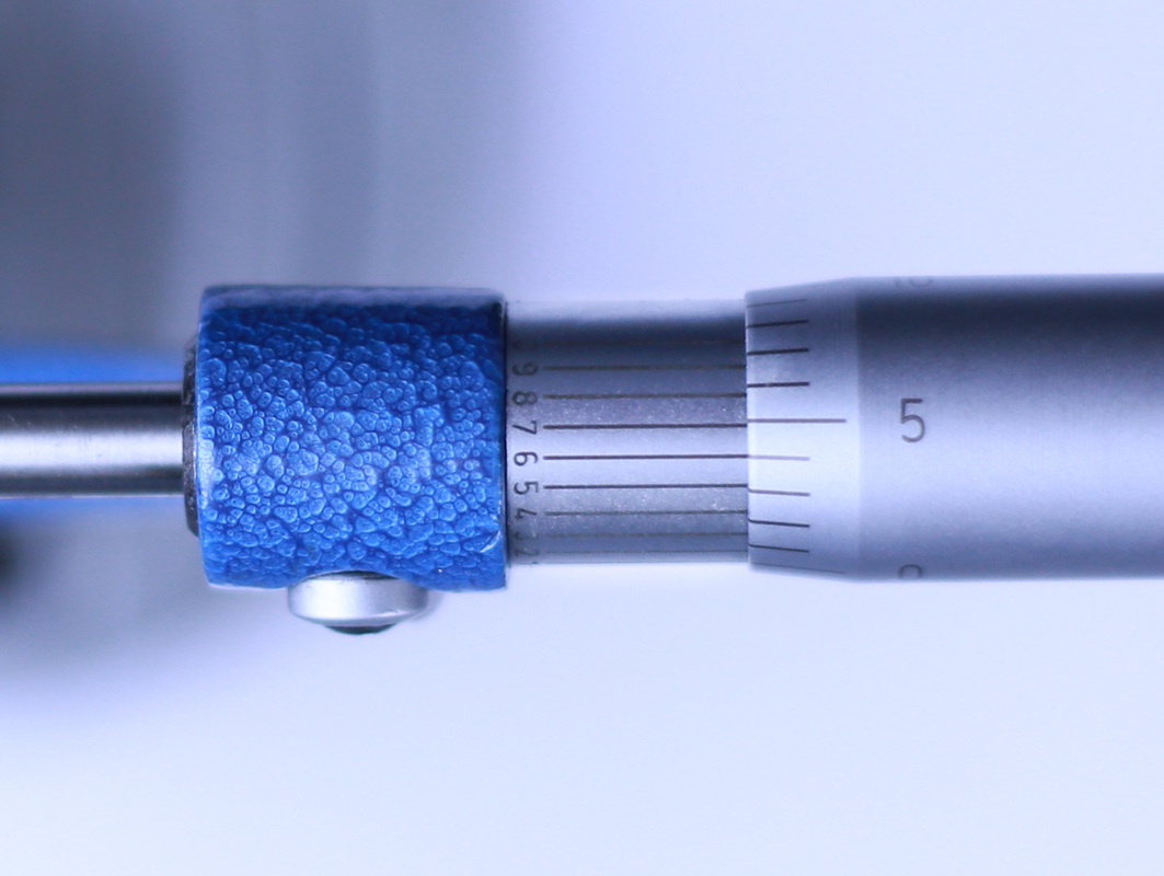
The sleeve reads 0.525”.
The sleeve reads 0.525”.
As you can see above, the thimble shows a little more than 0.005”. So far our measurement is 0.530" because we add the value from the thimble to the value from the sleeve.
Last, we look at the Vernier scale. The horizontal line on the thimble matches perfectly with the fifth line on the Vernier scale so we must add 0.0005" to the sleeve and thimble readings. This results in a final value of 0.5305" (0.525" + 0.005" + 0.0005"). Again using a 2 - 3" micrometer the total value is 2.5305".
For metric micrometers the process is exactly the same, however the sleeve is divided into 0.5mm graduations. The thimble features 50 - 0.01mm graduations. The Vernier scale is divided into 5 - 0.002 graduations.
Calibrating Micrometers
Each micrometer will require calibration prior to use to ensure that it is accurate. A 0-1” micrometer is the easiest to calibrate because when its measuring faces are closed all the way together the micrometer should read "0". For micrometers which measure sizes larger than 1 inch, standards or gage blocks will be needed to calibrate the micrometer. The calibration process for all micrometers is the same apart from the use of standards to calibrate the larger micrometers which don’t close all the way.
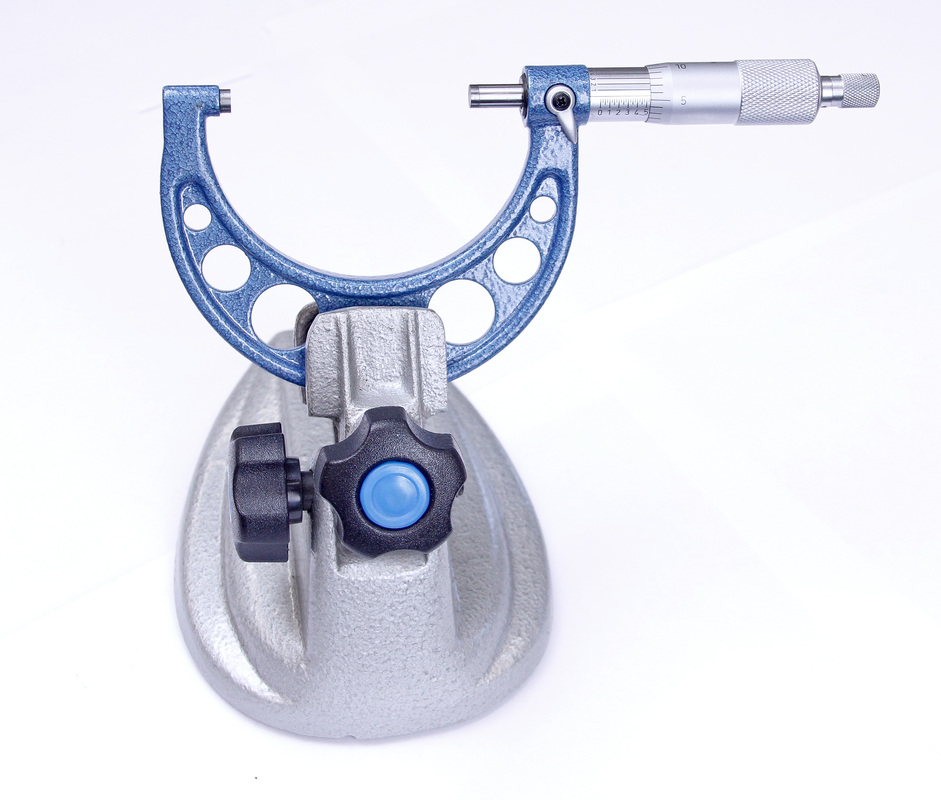
- Set the frame of the micrometer in a micrometer stand. By using the stand you will free up one hand and won’t transfer your body heat into the micrometer.
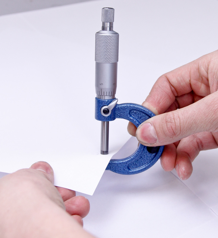
2. Lightly clamp a piece of paper between the measuring faces (0-1") and slide the micrometer across the paper to clean the measuring faces. For larger micrometers wipe the paper across each of the measuring faces using your fingers.
|
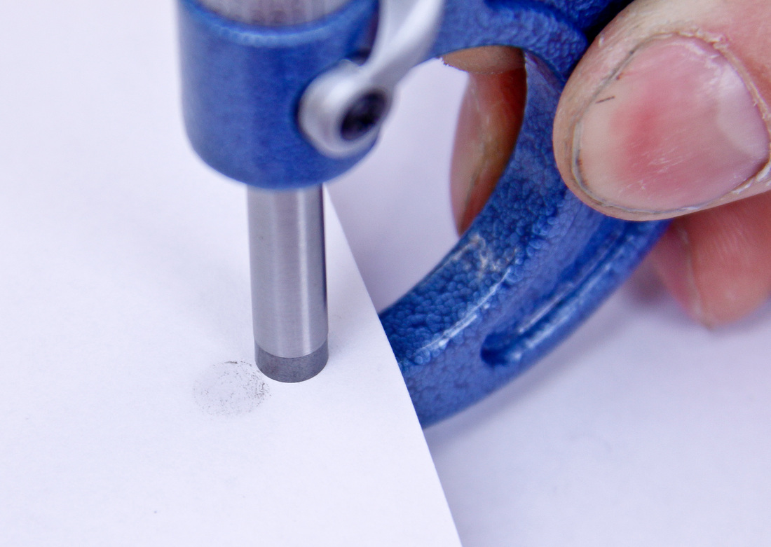
|
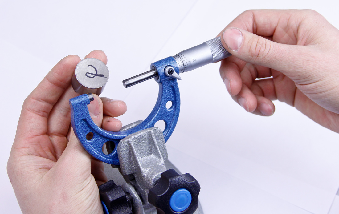
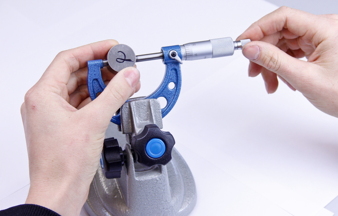
3. Close the measuring faces (0-1”) or insert the appropriately sized measuring standard. Read the micrometer and see if the sleeve, spindle, and Vernier scale align precisely at "0". If the micrometer does read "0" open and close the measuring faces a few more times to confirm.
4. If the micrometer does not read "0" it will need to be adjusted. With the measuring faces closed or the standard inserted, follow the adjustment procedure outlined for your specific type/brand of micrometer. Carefully zero the micrometer then tighten any adjusters. Open and close the micrometer a few times to confirm it has been zeroed. Once the micrometer repeatedly reads "0" it is ready to use.
Hot Tip: Sometimes you can find a machinist that is willing to let you check your micrometer and standards against theirs. This is especially useful when checking the accuracy of cheaper micrometer sets. Compare the accuracy of the cheaper set to a high dollar set of Starrett’s or Mitutoyo’s. This is great for engine building peace of mind!
How To Use:
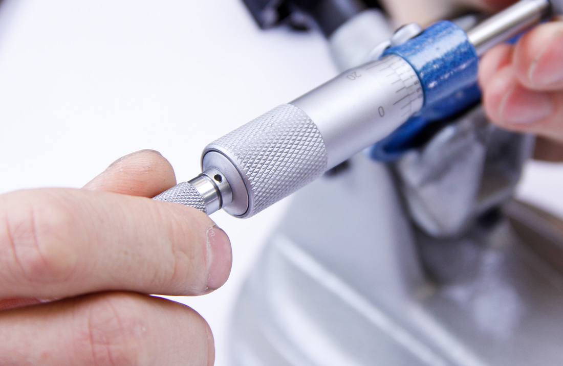
1. Open the spindle so the piece being measured can fit between the measuring faces.
Hot Tip: Sometimes you can find a machinist that is willing to let you check your micrometer and standards against theirs. This is especially useful when checking the accuracy of cheaper micrometer sets. Compare the accuracy of the cheaper set to a high dollar set of Starrett’s or Mitutoyo’s. This is great for engine building peace of mind!
How To Use:
1. Open the spindle so the piece being measured can fit between the measuring faces.
2. Gently turn the ratchet until the measuring faces start to touch the part being measured.
3. Make sure the part is square to the measuring faces. For cylindrical parts, slide the part between the measuring faces to make sure you are measuring the diameter of the part at its widest point.
4. Turn the ratchet stop until it clicks a few times. The correct pressure has now been applied to the part being measured. If the micrometer doesn’t have a ratchet stop, turn the spindle until light pressure has been applied to the part. The part should still be able to move between the measuring faces, dragging just slightly.
4. Turn the ratchet stop until it clicks a few times. The correct pressure has now been applied to the part being measured. If the micrometer doesn’t have a ratchet stop, turn the spindle until light pressure has been applied to the part. The part should still be able to move between the measuring faces, dragging just slightly.
5. Use the lock to lock the spindle in place.
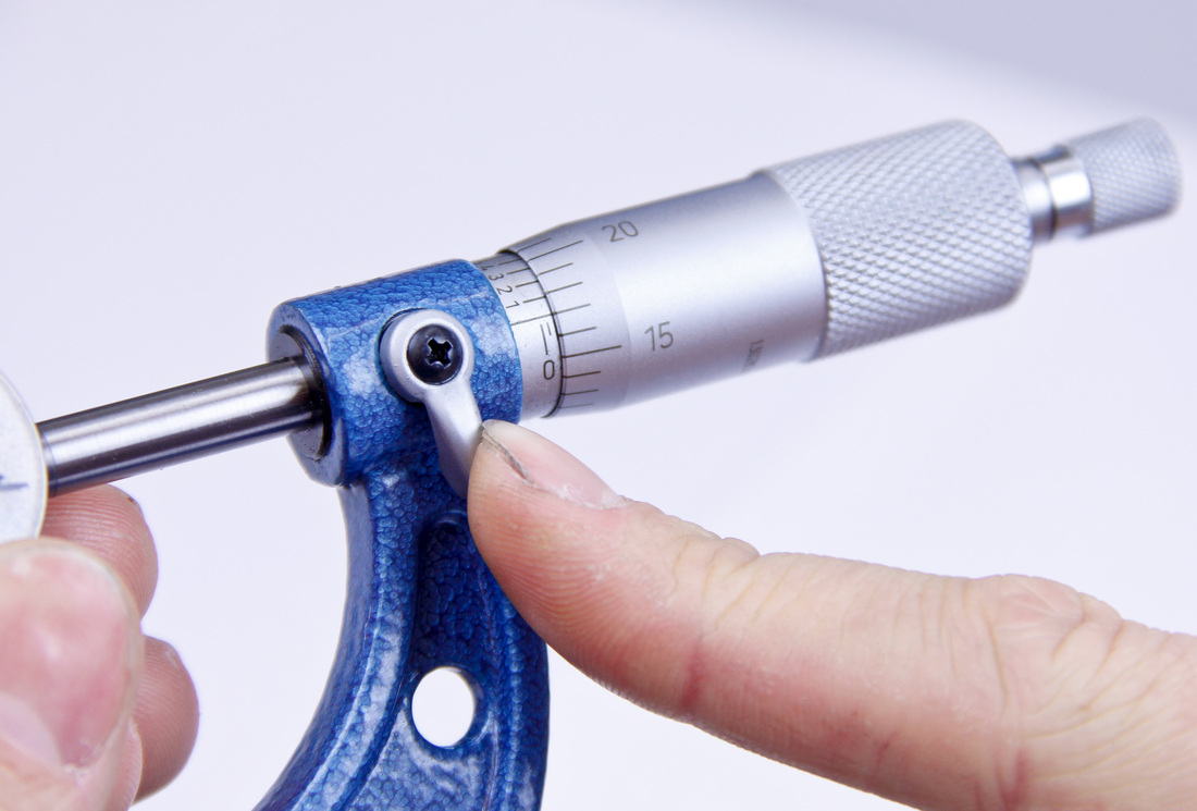
6. Remove the part being measured.
7. Read the micrometer. Remember to start with the whole number value, then record the value on the sleeve, add the value on the thimble, and finally add the value on the Vernier scale to the sleeve and thimble readings.
8. Don’t forget to unlock the micrometer prior to taking another measurement.
Hot Tip: For measurements requiring the utmost accuracy take 3 to 5 measurements. Then take the average of your measurements and use this value as the measured value.
Hot Tip: For measurements requiring the utmost accuracy take 3 to 5 measurements. Then take the average of your measurements and use this value as the measured value.
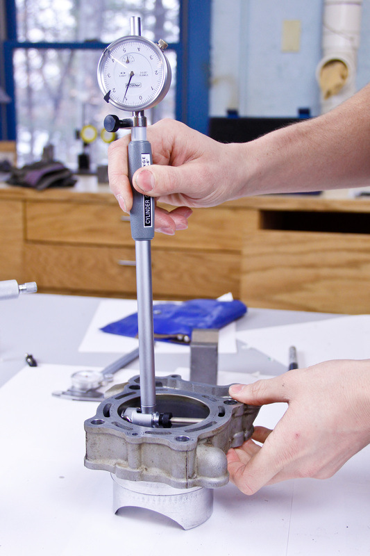
Dial Bore Gauge
A dial bore gauge is a very versatile and accurate tool used to measure internal diameters. The dial bore gauge features a long shaft with a dial indicator affixed to one end and a measuring head attached to the other. Most measuring heads feature interchangeable extension rods so the gauge can be used to measure a variety of different bore sizes. To quickly and accurately measure cylinder bores the dial bore gauge is the best tool for the job. The dial bore gauge is a comparative measurement tool, meaning that it must be set to a specific diameter prior to measuring.
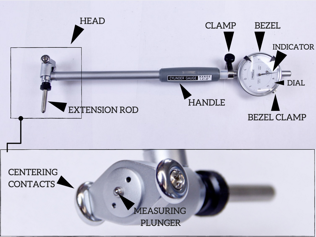
Dial bore gauges come in different size ranges, accuracies, and resolutions. Dial bore gauges are not a cheap measurement tool so take care to research quality, determine your personal measuring needs, and access your budget before purchasing. For dirt bike engine building finding a dial bore gauge which can measure from 1.4 - 6” (35.5 - 152mm) will cover the majority of applications. If you don’t work with any small bores a gauge with a range from 2 - 6” would be fine. The accuracy and resolution of the gauge should be 0.0001” (0.0025mm).
Calibrating the gauge can be done several different ways. The most accurate way to calibrate a dial bore gauge would be to use a ring setting gauge which is close to the bore diameter being measured. While this is the best way, ring setting gauges are expensive and may not be worth the investment if the dial bore gauge won’t be used frequently to measure a specific diameter. If you were to build an array of engines all with different bore sizes it would be necessary to have a ring gauge for each bore size. This would be cost prohibitive and is a difficult cost to justify for the amateur builder.
A more economical calibration method is to use a micrometer to set the diameter of the dial bore gauge. A micrometer is adjusted and set to the bore size being measured and the gauge is calibrated based on the size of the micrometer. One pitfall with this method is that the micrometer must be very reliable and accurate in order for the bore gauge to be accurate.
Special bore gauge setting tools are also available. Bore gauge setting tools work similar to a micrometer, however one setting tool will usually cover all the sizes the bore gauge is capable of measuring. Most setting tools come with their own setting gauge to ensure the tool is accurate.
One final method worth mentioning involves using gage blocks and plates to set the bore gauge. The gage blocks are added together until they equal the desired bore diameter. Precision ground plates are set at each end of the gage blocks and the assembly is lightly clamped together. The bore gauge can then be calibrated between the ground plates.
Where to Use: Cylinder Bore
Reading Dial Bore Gauges: The gauge face of a dial bore gauge is similar to other dial gauges. The gauge is divided into equal graduations representative of the tools resolution. A needle pointer indicates the tools measurement.
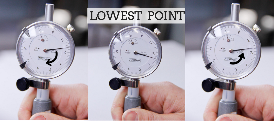
Reading measurements from a dial bore gauge is a little different than other tools. To use a dial bore gauge correctly the tool is rocked back and forth in the cylinder bore. As the tool starts out of square with the bore it will read high, as it becomes square it will read its lowest value, then as it proceeds past square it will read high again. The correct point to take the measurement from is when the dial bore gauge reads at its lowest value just before the needle starts to change direction.
Calibrating the gauge can be done several different ways. The most accurate way to calibrate a dial bore gauge would be to use a ring setting gauge which is close to the bore diameter being measured. While this is the best way, ring setting gauges are expensive and may not be worth the investment if the dial bore gauge won’t be used frequently to measure a specific diameter. If you were to build an array of engines all with different bore sizes it would be necessary to have a ring gauge for each bore size. This would be cost prohibitive and is a difficult cost to justify for the amateur builder.
A more economical calibration method is to use a micrometer to set the diameter of the dial bore gauge. A micrometer is adjusted and set to the bore size being measured and the gauge is calibrated based on the size of the micrometer. One pitfall with this method is that the micrometer must be very reliable and accurate in order for the bore gauge to be accurate.
Special bore gauge setting tools are also available. Bore gauge setting tools work similar to a micrometer, however one setting tool will usually cover all the sizes the bore gauge is capable of measuring. Most setting tools come with their own setting gauge to ensure the tool is accurate.
One final method worth mentioning involves using gage blocks and plates to set the bore gauge. The gage blocks are added together until they equal the desired bore diameter. Precision ground plates are set at each end of the gage blocks and the assembly is lightly clamped together. The bore gauge can then be calibrated between the ground plates.
Where to Use: Cylinder Bore
Reading Dial Bore Gauges: The gauge face of a dial bore gauge is similar to other dial gauges. The gauge is divided into equal graduations representative of the tools resolution. A needle pointer indicates the tools measurement.
Reading measurements from a dial bore gauge is a little different than other tools. To use a dial bore gauge correctly the tool is rocked back and forth in the cylinder bore. As the tool starts out of square with the bore it will read high, as it becomes square it will read its lowest value, then as it proceeds past square it will read high again. The correct point to take the measurement from is when the dial bore gauge reads at its lowest value just before the needle starts to change direction.
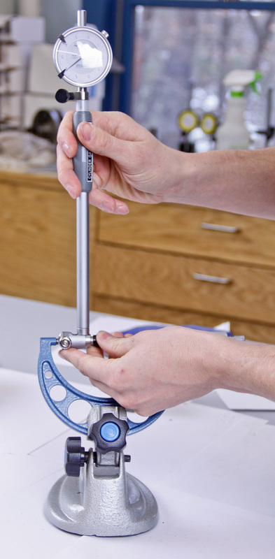
Calibrating a Dial Bore Gauge: Micrometer Method
1. Calibrate a micrometer with a resolution of 0.0001” which is capable of measuring the diameter of the cylinder. See the micrometer calibration section for specific details. Set the micrometer to the desired size and lock it in position.
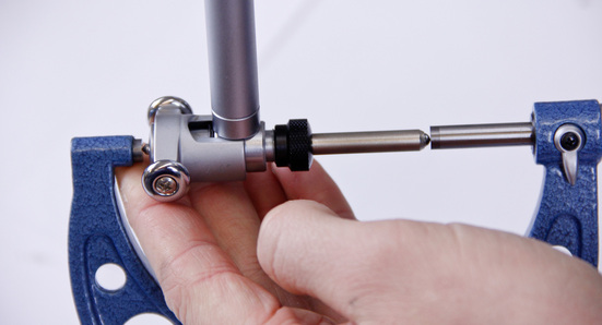
2. Gently clean the dial bore contact points with your finger tips.
1. Calibrate a micrometer with a resolution of 0.0001” which is capable of measuring the diameter of the cylinder. See the micrometer calibration section for specific details. Set the micrometer to the desired size and lock it in position.
2. Gently clean the dial bore contact points with your finger tips.
3. Insert the dial bore gauge between the micrometer measuring faces.
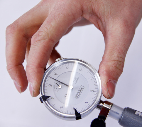
4. Carefully rock the dial bore gauge back and forth. Note the lowest value the needle reads and how far the dial must be turned so the "0" on the gauge face aligns with this point.
5. Rotate the dial face and zero the dial bore gauge to the lowest needle reading.
6. Reinsert the dial bore gauge between the micrometer measuring faces. Gently rock the gauge back and forth. Confirm the lowest reading of the bore gauge is "0". If the gauge doesn't quite read "0" remove the dial bore gauge and rotate the dial again. Recheck and repeat this process until the dial bore gauge reads "0" between the measuring faces of the micrometer.
7. Check the calibration a couple of times for repeatability.
Hot Tip: Use a micrometer stand to hold the micrometer while calibrating the dial bore gauge. This makes the process much easier and frees up an otherwise busy hand to assist with calibration.
If you’re having trouble keeping the dial bore gauge tips between the measuring faces of the micrometer, try slipping a quarter inch piece of tubing over the end of the micrometer. The tubing won’t affect the measurement but will help to keep the dial bore gauge positioned.
If you don’t have a micrometer stand but have a vice, the micrometer can be gently set in the vice. Use a rag to pad the micrometer ensuring the micrometer won’t be damaged by the jaws of the vice.
Alternatively the dial bore gauge could be carefully clamped in the vice and the micrometer left free to rock back and forth during calibration.
Calibrating a Dial Bore Gauge: Ring Setting Gage Method
The process for calibrating a dial bore gauge using a ring setting gage is similar to that of calibrating the gauge using a micrometer. Simply follow the steps outlined for calibrating the gauge using a micrometer but enjoy the fact that you don’t have to first calibrate the micrometer! In addition the dial bore gauge will be much easier to center in the ring setting gage and you won’t need a third hand.
How To Use:
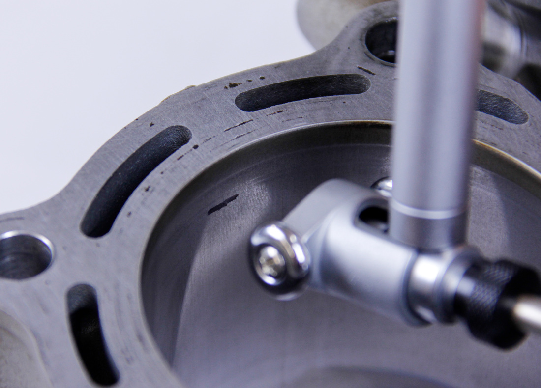
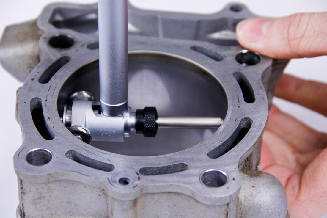
1. Insert the dial bore gauge into the cylinder bore. Set the end of the contact head at the desired height in the bore and gently touch the plungers to the bore.
Hot Tip: Use a micrometer stand to hold the micrometer while calibrating the dial bore gauge. This makes the process much easier and frees up an otherwise busy hand to assist with calibration.
If you’re having trouble keeping the dial bore gauge tips between the measuring faces of the micrometer, try slipping a quarter inch piece of tubing over the end of the micrometer. The tubing won’t affect the measurement but will help to keep the dial bore gauge positioned.
If you don’t have a micrometer stand but have a vice, the micrometer can be gently set in the vice. Use a rag to pad the micrometer ensuring the micrometer won’t be damaged by the jaws of the vice.
Alternatively the dial bore gauge could be carefully clamped in the vice and the micrometer left free to rock back and forth during calibration.
Calibrating a Dial Bore Gauge: Ring Setting Gage Method
The process for calibrating a dial bore gauge using a ring setting gage is similar to that of calibrating the gauge using a micrometer. Simply follow the steps outlined for calibrating the gauge using a micrometer but enjoy the fact that you don’t have to first calibrate the micrometer! In addition the dial bore gauge will be much easier to center in the ring setting gage and you won’t need a third hand.
How To Use:
1. Insert the dial bore gauge into the cylinder bore. Set the end of the contact head at the desired height in the bore and gently touch the plungers to the bore.
|
|
2. Slowly pivot the handle of the bore gauge so that the contact head and handle start to become square with the bore.
3. Simultaneously, while pivoting the gauge watch the indicator.
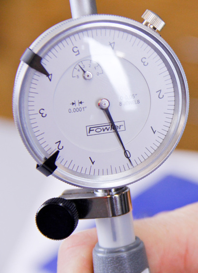
4. Once the gauge is square to the bore the dial gauge should read at its lowest value.
4. Once the gauge is square to the bore the dial gauge should read at its lowest value.
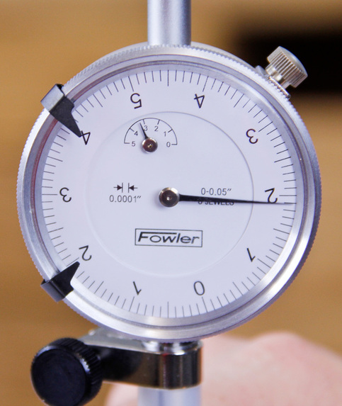
In the photo above the needle is at its lowest point. The bore gauge reads 0.0019" larger than the calibrated size.
5. As the gauge passes through the point of being square the gauge needle will change directions indicating the length of the gauge is starting to get longer.
5. As the gauge passes through the point of being square the gauge needle will change directions indicating the length of the gauge is starting to get longer.
6. The point at which the needle reads the lowest value just before it begins to change direction is the point at which the measurement should be taken.
7. Record the measurement.
8. To determine total bore size either add or subtract the measured value from the calibrated value of the micrometer or ring setting gauge. Consider an example where the micrometer was set to 3.7795” (96.0000mm) and the dial bore gauge was calibrated to this value. Once the bore gauge was inserted into the cylinder the gauge needle changed directions at the positive value of 0.0003” (0.0076mm). By adding 3.7795” (96.0000) and 0.0003” (0.0076mm) together the final bore diameter ends up being 3.7798” (96.0069mm).
9. Don’t forget to take a few measurements when measuring critical dimensions of parts.
Hot Tip: For comparing taper and out-of-roundness, simply compare the measurements taken from the bore gauge to one another. There’s no need to add the calibrated bore diameter into the mix.
As you can see the world of measurement tools, their capabilities, and how to use them during your rebuild is vast and requires a hefty amount of knowledge. Next week I will be discussing in depth the remaining six tools you can use for precision measuring as an at-home mechanic. Be sure to share this post with any of your wrenching buddies and keep your eyes peeled for our next post, Precision Measuring For The At-Home Mechanic // Part Three.
Are you a dirt bike engine building enthusiast? Do you love working on your engine and bringing your four stroke to its highest state of tune? Then you are going to love the in-depth precision engine building knowledge I am providing for at-home mechanics and experts in The Four Stroke Dirt Bike Engine Building Handbook. This boos is available as both an eBook and in print. Right now we have an awesome deal running where all website visitors get 20% off when they enter the discount code: fixityourself2015 before purchasing. To learn more about the book, check out the Table of Contents, and hear some testimonials, click here.
If you want to share a tip, ask a question, or leave a comment please do so!